
T200Quick ViewView Full Details |
Description: The RS485 serial interface on Tracker instruments are electrically isolated and have four protocols including the widely used Modbus RTU. This allows a centralised "Master" device (e.g. a PC) running a data acquisition program to pole "slave" devices to receive real time data. This data can be viewed graphically in real time, archived for review later and give alarm alert if the values are outside preset limits. Some system also allow values to be sent from the Master to the slaves, e.g. Setpoint values. The following instruments have a RS485 interface fitted as standard: • Tracker 220 Series 4/5-Digit High accuracy Process inputs • Tracker 240 Series 4/5-Digit Load Cell Indicators • Tracker 250 Series 5-Digit Melt Pressure Indicators • Tracker 260 Series 5-Digit LVDT Indicators • Tracker 280 Series 5-Digit Timer/Counter/Frequency Indicators • Tracker 300 Series DIN rail mounted instruments You can connect up to 32 devices to a single master device in a multi-drop configuration. You can control the display and analogue output via the serial interface, allowing any device to be used as a remote display or control device. |
T200Quick ViewView Full Details |
Description: All Tracker instruments have alarm output options with volt free relay contacts and TTL outputs on some models. On the panel meters an alarm state message can be flashed on the display along with the measured value. The following instruments have alarm outputs and options: • Tracker 211 4-Digit Low Cost, 1 C/O as standard, optional +1 C/O +1 N/O • Tracker 222 4-Digit High Accuracy, 2 C/O as standard • Tracker 224 5-Digit High Accuracy, 2 C/O as standard • Tracker 244 5-Digit Load Cell Indicator, 2 C/O as Standard • Tracker 245 5-Digit Load Cell Indicator, 4 TTL outputs as standard • Tracker 254 5-Digit Melt Pressure Indicator. 2 C/O as standard • Tracker 255 5-Digit Melt Pressure Indicator, 4 TTL outputs as standard • Tracker 264 5-Digit LVDT Indicator, 2 C/O as standard • Tracker 265 5-Digit LVDT Indicator, 4 TTL Outputs as standard • Tracker 284 5 Digit Timer / Counter, 2 C/O as standard • Tracker 285 5-Digit Timer / Counter, 2 TTL outputs as standard • Tracker 321 & 332 DIN Rail, +4 C/O when 341 logic expansion module fitted • Tracker 331 DIN rail, 1 N/O as standard, +1 N/O option, +4 C/O with 341 C/O = Volt free Change Over contacts, N/O = Volt free Normaly Open contacts On the Tracker 211 low cost series the following alarm parameters are available: • Alarm type - none, high, low • Alarm message display - on off (for all alarms) • Setpoint (max 3 alarms) • Hysteresis All other instruments (per alarm): • Alarm Type - none, high, low, deviation (band) • Setpoint (max 4 alarms) • Deviation high • Deviation low • Latching - On, off • Output selection (which outputs switch if any) • On delay (seconds) • Off delay (seconds) • On hysteresis • Off hysteresis • Edit setpoint - On, off(operator access at run time) • Alarm message display - On, off • Relays energised or de-energised in the alarm state The hysteresis facility stops noisy signals switching outputs rapidly (relay chatter). High and low deviation creates a band around the setpoint value. The alarm will be activated if the measured value is out of this band. On and off delay times can be set to stop fleeting alarms. The measured value must be continuously in the alarm condition for the time set before the alarm becomes activated. Individual alarms configured as latching or non-latching. Latched alarm require to be acknowledged by the front panel push buttons or, on models fitted with status inputs, via remote volt free contacts. |
T200Quick ViewView Full Details |
Description: Filling sequence The Tracker 244 and 225 have 2 relays with volt free contact or 4 TTL outputs respectively. These outputs can be used for alarms or for a batch control filling sequence. The filling modes can be "Fill", where the container to be filled is on the load cells, or "Loss of weight" where the product's reservoir/tank is on the load cells. |
T280Quick ViewView Full Details |
Applications: • Pulse Rate - Scaled pulses for rate (e.g. Litres per minute) • Pulse Totalisation - Pulses scaled to engineering units • Frequency Measurement - Scalable to engineering units (e.g. rpm) • Up/Down Counting (Uses both channels) • Batch control • Position Measurement with encoders (Uses both channels) • Encoder quadrature measurement (Uses both channels) • Timing Description: Maths functions include: • Tare, zero, pre-set, Max /Min • Channel 1 + Channel 2, Channel 1 - Channel 2 • Elapsed time, Total Time, Average Time • Period cycle time, Ratio of a period, Ratio channel 1 v Channel 2 |
Synergy
Quick ViewVideoView Full Details |
Description: Reduced Energy Consumption and Increased Reliability are key objectives for all plant owners and managers. Fairford soft starters can deliver both. Fairford, supported by our distributor network have experience of installing soft starts in every application, in every industry, on every continent, see the case studies for examples. In industry 75% of all energy is used by electric motors and surprisingly the majority of motor operate at below 50% load, the unique Fairford iERS technology ensures that fixed speed motor run as efficiently as possible. With the fullest possible range of soft starts including single-phase, 3-phase, low voltage and medium voltage options, Fairford has the products and the experience to deliver effective solutions to all industrial sectors. |
DL24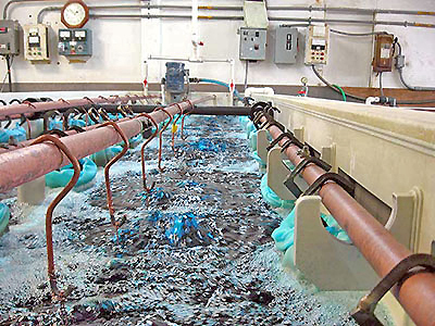
Quick ViewView Full Details |
Plating
or metal finishing is the process of depositing a metal coating on an object
such as chrome, gold, silver, nickel or zinc. Plating improves the appearance,
corrosion resistance, hardness and wear ability of parts. The most common
plating processes are electroplating and electroless plating. Electroplating
uses electric current to reduce dissolved metal cations to coat an electrode,
and is primarily used to change the surface properties of metal parts.
Electroless plating is a chemical technique that relies on the presence of a
reducing agent, such as sodium hypophosphite that reacts with metal ions to
deposit metal on plastic or metal parts. In either process, parts are dipped
into a series of plating tanks or baths that clean, etch, plate and rinse
coated parts to specification. Plating tanks are often rectangular, open top,
plastic or fiberglass baths that are 3’ to 6’ in height. Normally placed in a
row with common walls between each tank, plating systems can have as few as 3-4
tanks or as many as 30 tanks in a single line. Depending upon the system, parts
are manually or automatically lifted, lowered, raised and moved from one tank
to the next. Hence plating tanks, including the space required for parts
dipping and movement are generally crowded, busy environments. The primary
requirement for this application is to monitor the liquid level, ensuring that
tank levels are maintained in a near full state without parts displacement, and
a full state with parts displacement. So the two operational levels vary based
upon the size or displacement of the parts to be plated. |
DL24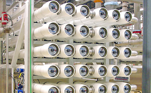
Quick ViewView Full Details |
Ultrapure
or high purity water has been purified to tight specifications to remove
contaminants that can negatively affect people, products or equipment. These
may include organic or inorganic compounds, bacteria, toxins, particulates and
gases. Ultrapure water is widely used in the semiconductor, electronic,
medical, pharmaceutical, biotech and food industries. Reverse osmosis and
deionized water systems are different water purification processes. Reverse
osmosis is a filtration method that removes molecules and ions from water as it
passes through membranes. Deionization is a chemical method that uses specialty
resins to exchange hydrogen and hydroxide ions for dissolved minerals, and then
recombine them back into purified water. The ultrapure water that results from
either process is contained in a storage tank for use in high purity
applications. The storage tanks have two basic control systems, one to add
liquid into the tank, and one to remove liquid from the tank into process. The
primary requirement for this application is to monitor the liquid level,
automatically refill the tank, and prevent it from overflowing or running dry. |
DL24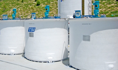
Quick ViewView Full Details |
Before
wastewater can be reused or released to the municipal sewer or environment, it
must be treated to acceptable standards. Depending upon the upstream process,
this often entails the removal of solids or oils, and pH neutralization of the
remaining wastewater. When a solution is neutral, its salt is formed from equal
weights of acid and base, and pH or the measure of free acidity or alkalinity
in water, is used to determine its state relative to a pH neutral value of 7.0.
Measured on a scale of 0-14, solutions with a pH of 6.9 or less are acidic, and
solutions with a pH of 7.1 or higher are alkali. Bases neutralize acids and
acids neutralize bases. Hence, the task of a pH neutralization system is to
measure and adjust the influent pH value to an acceptable range through the
addition of acid or base, prior to discharging the treated effluent.
Neutralization systems are made in two types including batch and continuous. In
a batch system, influent fills the tank, the pH adjustment process begins and
when the tank contents are neutralized, the treated effluent is discharged in a
cycle. In a continuous system, the tank remains full all the time. As one
gallon of influent enters the tank, one gallon of effluent exits the tank. If
the pH of the influent differs from that within the tank, its quickly
neutralized as it mixes. Both systems include a neutralization tank, acid and
caustic metering pumps, mixer, pH controller and level sensor. The
neutralization tank is typically a plastic or fiberglass tank with an open or
enclosed top. The primary requirement for this application is to monitor the
liquid level, ensuring that the levels are maintained within their operational
ranges, and either emptying and refilling the batch system, or maintaining the
level of the continuous system. |
LR30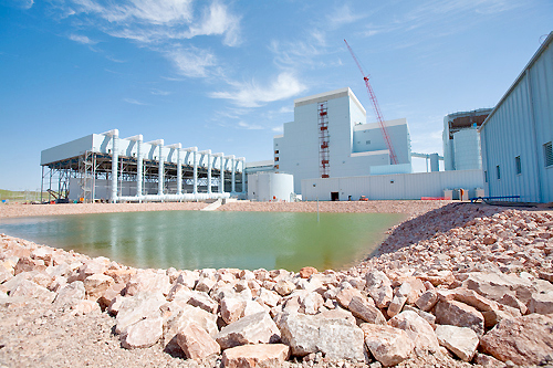
Quick ViewView Full Details |
Reservoirs
store large volumes of water and can be a natural or man-made lake, pond or
impoundment structure. They can be gravity or pump fed. Reservoirs are
typically created by controlling a stream that flows into a natural body of
water, constructing a dam within a river valley, excavating a basin into flat
ground or constructing an above grade retention pond. No matter the type,
reservoirs play a critical role in water supply management, irrigation, flood
control and public recreation. Reservoirs are commonly used to balance flow in
river or stream networks, taking in and storing water during peak
precipitation, and releasing water during dry periods. In-flow, storage and
out-flow balancing is achieved by monitoring the reservoir level and weather
forecasts, and releasing water ahead of large storms to free up capacity.
Depending upon the reservoir type and size, they range from 3’ to 50’ in depth.
The primary requirement for this application is to monitor the liquid level,
balance the in-flow and out-flow, and prevent the reservoir from overflowing or
running dry. |
LR30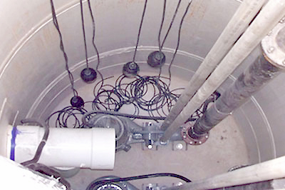
Quick ViewView Full Details |
Industrial
lift stations collect wastewater streams from processes and transfer their
contents into wastewater treatment. Lift stations are normally below grade,
gravity fed cylindrical or rectangular sumps, constructed of concrete or
fiberglass with depths ranging from 6 to 30 feet. There are three main
application segments in the lift station market including industrial
wastewater, municipal sewer and municipal storm water. Wastewater enters lift
stations from the top and is removed from the bottom using one or two transfer
pumps. The pumps can be located above grade near the lift station or submersed
within the sump. Lift stations are typically crowded, dynamic environments with
ladders, pipes, pumps, rails, electrical, sensors and waste streams pouring in
from various sources. Wastewater can be corrosive, dirty, foaming, viscous,
oily or vaporous, making it difficult to measure reliably. The primary
requirement for this application is to monitor the liquid level, periodically
transfer the wastewater from the lift station to another location, and prevent
it from overflowing or running dry. |

