

Winch Load Monitoring
APPLICATION: LCM Systems manufacturer and supply winch load monitoring systems that provide winch line load data. This improves operational safety by allowing operators to take preventative action in the event that winch loads exceed pre-determined safe limits. The load cells that we use for this application are robust, reliable and built to withstand harsh operational environments. They can be fitted to new equipment or retrofitted without any modifications to the winch. We can supply standard load pins or dual axis load pins that take into account wrap angles. These load pins incorporate separate strain gauges in both the X and Y axis, so that the effect the wrap angle has on line loads is taken into account.
In addition to load pins, other types of load cell can be used to monitor winch loads and include load links and compression load cells. These are often used when a highly accurate solution is needed or where the use of a load measuring pin is not practical/possible.
In addition to providing improved safety, the historical data-logging of winch loads gives asset owners and managers additional information that can be used for scheduling routine maintenance and to demonstrate winch performance and integrity. |
Winch Tension Monitoring & Control
APPLICATION: LCM Systems winch tension monitoring and control systems have been designed to deliver critical information that is required for safe winch operation. Our solution comprises a load measuring pin that replaces an existing load bearing pin in the winch sheave and accompanying instrumentation and/or load display. We can also supply load pins with a variety of signal outputs that can be integrated directly into existing PLC systems.
Our load pins have been designed and manufactured for long-term continuous operation, providing users with real time data on line tension. This is particularly critical for winches on offshore vessels and oil platforms, where deck crew routinely carry out demanding operations at sea, often during severe weather conditions. This work can involve handling heavy wires, chains and ropes under tension, which can expose the deck crew to the risk of serious injury in the event of line failure.
With the use of a winch tension monitoring and control monitoring system, such instances can be avoided. Should tensions reach pre-set limits, the system can generate alarms that allow operators to take preventative action before any damage occurs to the winch or line and personnel put at risk.
Our winch tension monitoring and control systems can include simple stand alone winch tension monitoring to comprehensive monitoring and control packages. Zone 1 and 2 ATEX/IECEx hazardous area systems are also available. |
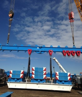
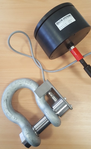
Verification of The Load Capacity of A Lifting Beam ______________________________________________________ The requirement was for 55te telemetry load shackles that could function in the sub-zero temperatures of the Canadian winter, so had to be robust enough to operate consistently in temperatures as low as -40°C. The customer had seen our standard TELSHACK-B load shackles on our website, but as they are rated to -20°C, were not quite sufficient. Utilising over 30 years of load measurement experience, our design engineers were able to adapt the design to incorporate component parts with lower temperature ratings to make it suitable for their requirement.
A total of 14 telemetry load shackles were supplied, which were fitted to a lifting beam to enable load testing to be carried out. Suspended from a 750te crane, the lifting beam has 14 sliders along its length, each of which were fitted with a load shackle. Any number of sliders can be used for a lift, depending on the size and weight of the item being lifted. The sliding mechanisms enable the lifting strops to be positioned in such a way as to ensure the load is evenly distributed along the length of the lifting beam and that it is evenly balanced.
For the purposes of testing the beams load capacity, a number of counter weights were lifted and the resulting loads recorded. The photograph below shows two load shackles in use, but over the course of the tests all 14 were in operation. The load shackles performed to expectations and the customer subsequently ordered a further 14 load shackles for the testing of another lifting beam. |
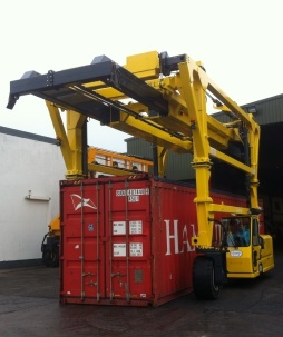
Container Weight Verification ____________________________________________________ We were contacted by a longstanding customer about the feasibility of supplying them with a SOLAS compliant container weighing system. We had been supplying this specialist straddle carrier and forklift manufacturer with container weighing systems for around five years, which they offered as an option on their straddle carrier range. With the introduction of updates to the SOLAS regulations, which stipulates that all containers must have a verified weight prior to shipping, they wanted a bespoke system to meet the standard that could be fitted to their equipment.
To meet the new legislative requirements, LCM Systems had to load pin location redesign the electronics of their existing system, and also introduce a new tablet display that showed the load on each individual pin and the total weight. Two existing load bearing pins were replaced with custom designed 25 tonne load measuring pins, which connect to an interface module where the mV/V output signal is converted to RS485 and the data then sent to the in-cab tablet display.
The new system was designed with pre-wired cable assemblies for connection to the interface module to allow installation to be carried out by untrained personnel, and also to facilitate fast and easy replacement of cables in the event of any becoming damaged. The tablet display, in addition to showing weight information, also has an in-built function that only allows the weight to be recorded once stable to ensure accuracy. It also includes a tare function and the facility to enter container numbers and generate reports. |
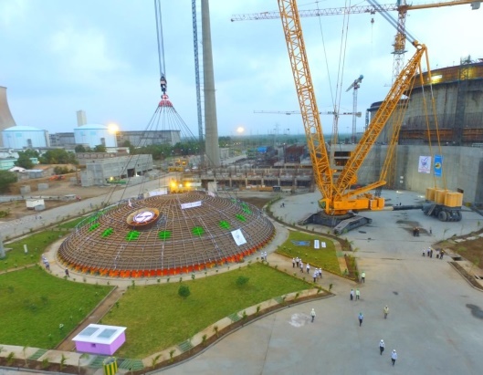
Heavy Lift Load Distribution Monitoring ____________________________________________________ An engineering and construction contractor, were commissioned to build a nuclear containment building at Kakrapar Atomic Power Plant. As part of the project they needed to lift and position a 47 metre diameter and 8.25 metre high inner containment dome liner, which had been built as a single unit. Because of the unique geometry of the dome and its 365 tonne weight, a balanced lift with equally distributed loads was vital to ensure a safe and successful lift. Eighteen lifting lugs were integrated into the dome liner, which were each fitted with a 55te wireless load shackle. At the customers request, a Crosby G2130 was used, rather than the smaller standard TELSHACK-B 55te, as it afforded a better fit within the lifting lugs.
LCM Systems also supplied a telemetry base station that detected the telemetry signals from the load shackles and transmitted them to a laptop, where engineers were able to view the loads on each lifting lug to ensure they remained uniformly loaded throughout the lift. With only 200mm clearance to work with, the Larsen & Toubro team lifted and placed the dome into position on top of the inner containment wall in just two hours, with alignment and anchoring taking a further three hours, after which the crane was released.
Larsen & Toubro commented “During test runs the turnbuckles where rotated according to the load displayed on all 18 load shackles to distribute the loads equally. This test was demonstrated to our client and the regulatory board, who were then happy to give their permission to lift the dome on the very next day.” |
Mooring Line Lonitoring of Fish Farm Tanks ____________________________________________________ A company who was looking for a monitoring system that could log the tension in mooring lines that anchored tanks used for the farming of salmon to the sea bed. They had seen the SHK-B load shackle range on our website, but as it would be located at a depth of around 4.5 metres, needed a special subsea version. An initial system was required for testing purposes (carried out in a tow tank), but if successful multiple systems would be fitted to the fish tanks out in the field. The requirement was to monitor the loads on the mooring lines to check that they did not exceed safe operational limits, particularly during severe weather conditions. A data logger was required to record measurement readings from the load shackle, which as well as being suitable for long term submersion underwater, also needed to be able to operate unattended for long periods between retrieval of the monitoring system for data download. LCM System engineers designed an IP68 enclosure for housing the data logging electronics, which was simple to open to facilitate easy access to the SD card and to replace the batteries. Lithium batteries were chosen to provide maximum battery life (around 90 days) and the data logger chosen featured low noise, high resolution and low power consumption, with the provision for 2 readings per minute. Data output was in Excel format for straight forward importation to a PC for analysis. The enclosure was connected to the load shackle via a 1 metre cable and housed within a float to keep it away from the mooring lines, to avoid any possibility of it becoming entangled during stormy seas. |

Scientific Equipment Displacement Monitoring ____________________________________________________ A customer looking to replace some displacement transducers they had purchased some years ago. These displacement transducers were being used to detect any linear movement in accelerators installed in the accelerator complex at CERNs underground laboratory on the French/Swiss border near Geneva (ariel view of complex shown below). These accelerators include the renowned Hadron Collider, which all work together to push particles to nearly the speed of light for scientific research. The displacement transducers are fixed into position over a weld or joint in various strategic points along the pipework, and if the joint/weld starts to pull apart, the extension rod moves in proportion to the level of displacement. Fractions of a mm can be detected, giving warning of any movement well in advance of any failure. In a laboratory the scale of the accelerator complex, any equipment breakdown could be catastrophic, so monitoring of structural integrity vital to the continued success of the project.
As the displacement transducers they had previously used were no longer manufactured and had been replaced by a newer model, the customer asked if they could have some modifications to better suit their application. Instead of having female rode end bearings at both ends they wanted the cable exit end modified to have a male rod end fitted to the actuator instead, with a 3mm rod end bore. This was because they didn’t use the bearing fixing system at this position, as the displacement transducer is clamped into place by the transducer body. Additionally the slight reduction in length would be beneficial in facilitating installation. LCM Systems made the required design amendments to the product, and ten were ordered for trial purposes.
The displacement transducer performed as expected and the custom design changes much better suited their requirements. As a result a further one hundred were ordered; enough to meet their requirements for the next 4 to 5 years. |
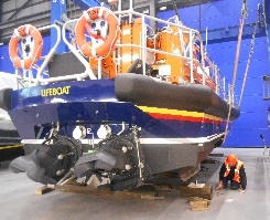
Vessel/Boat Weighing ____________________________________________________ A company was building a new Shannon Class of lifeboat at their new All-Weather Lifeboat Centre. As this is the first boat to be built in-house by the RNLI, there was a requirement to weigh it to ensure that the stability calculations are correct and the designed weight was achieved. A standard system of compression load cells and a wall mounted indicator was initially offered, however, after a follow-up with the Quality Technician, it was determined that a PC readout was required. After further discussions, the quote was finalised to include 4 x 25te stainless steel compression load cells (CPAs) with base plate connected to a junction box (DSJ4) containing 4 x DSC digital signal converters with RS485 output. This would allow the load from each load cell to be read individually as well as providing a total load. A small USB digital signal conditioner was also included for data conversion in a format suitable for direct download to a laptop/PC for load data display.
The customer went ahead and placed the order, which was manufactured and delivered within 4 weeks. Testing of the first lifeboat took place shortly after. One load cell was placed under the forward centre keel, one under each bilge keel aft and one under the centre keel in line with the bilge keels. The individual and combined weights were recorded and displayed on a laptop using the free DSC 24 Channel Logging software.
Each new build will be weighed in the same way and re-weighed when the boat is surveyed following sea trials. This allows the RNLI to see if there are any discrepancies between the results and potentially identify any issues, such as excessive water ingress into the bilges, for example. |
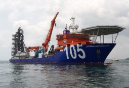
Pipe Laying Vessel Tension Monitoring System ______________________________________________________ A global provider of offshore and subsea oil field solutions contacted us about a load pin requirement for a pipe laying vessel. The company operate a fleet of lay vessels worldwide, and needed some replacement load pins for a tension monitoring system on a vessel fitted with an advanced Reel-lay system capable of both rigid and flexible pipelaying in up to 10,000 feet of water. The load pins they were looking to replace had previously been supplied by another company, but had become damaged due to a sub-standard adhesive being used to bond the strain gauges and poor water proofing. The customer was therefore looking for a new supplier that they could rely on to consistently provide quality load pins that offered long-term continuous operation.
The original enquiry was for 28 load pins, but a decision was later made to replace all load pins within the system. This comprised of 1 x 3200kN dual bridge load pin for the Aligner (with 1 spare), 4 x 450kN dual bridge load pins for the Straightener (with 1 spare) and 28 x 2500kN dual bridge load pins for the Tensioner Track (with 2 spares). Each load pin was connected to a waterproof enclosure housing two amplifiers, to give dual redundancy. The amplifier supplied a 4-20mA output which allowed connection to the vessels PLC system, to provide a complete tension monitoring system.
The pipe tension monitoring system allows pipe deformation to be controlled as it leaves the vessel through to installation on the sea bed, by keeping the pipe under tension as it moves through the various pay out equipment. The bending and axial stresses can then be kept within an acceptable range to stop excessive bending and kinking from damaging the pipe. By continuously monitoring the tension levels, the operator can make adjustments to the equipment as soon as a potential problem is identified, minimising any downtime. |
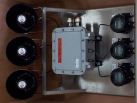
Umbilical Roller Sheave Load Monitoring ______________________________________________________ This requirement was for an international offshore drilling contractor that provides oilfield services for offshore oil & gas production, specialising in the ultra-deepwater sector. They needed ATEX Zone 2 rated load shackles with displays and alarms for one of their deep water drillships that was being deployed off the Angola coast on the ultra-deepwater Kaombo project. Due to their clients stringent rules regarding hazardous areas, they needed certified products in order to comply. LCM Systems designed a system to meet their requirements that comprised of 3 x 12 tonne load shackles and an ATEX junction box to be situated at the top of an A-Frame, which was wired to another ATEX junction box at its base and connected to 3 channel ATEX display and alarm system (see photo below). Also connected to this junction box was an additional display and alarm system located below deck in the driller cabin, which, because it was located in the Safe Area, was not required to be ATEX certified.
Due to the harsh operating environment, all cable supplied was RFOU (I) 250V armoured mud resistant
The load shackles were required to monitor the loads on umbilical roller sheaves as they payed out the hose to ensure that it did not become sagged and to check that the hydraulic hose reels were operating correctly. Each load shackle had its own display to show the individual loads, and all three were set to trigger an audio and visual alarm in the event of a pre-set limit being reached. A second display and alarm system was incorporated into the drilling cabin for remote system monitoring.
We subsequently received an identical order for the same system for another deep water drillship operator working on the same project. |