Connects a host controller to this product and provides isolation
(RS-232C and RS-422 are switchable).
USB (Cables/Adapters)
USB (Type A) Interface
Product Name
Model No.
Description
USB Front Cable (1 m)
CA5-USBEXT-01
Extension cable that attaches USB interface to the front panel.
USB Clamp Type A (1 port)
PFXZCBCLUSA1
Clamp to prevent disconnection of USB cable
(USB Type A, 1 port, 5 clamps/set)
USB (micro-B) interface
Product Name
Model No.
Description
USB Transfer Cable
PFXZUSCBMB2
Cable for transferring screen data from a PC (USB Type A) to
this product (USB micro-B)
USB (micro-B) Front Cable
PFXZCIEXMB2
Extension cable that attaches USB interface to the front panel.
USB ClampType mini B
ZC9USCLMB1
Clampto preventdisconnectionofUSB cable (for 1 port, USB Typemini B, 5 pieces/set)
*USB Clampmini-Bcan be used for optionalUSB micro-Bcables.
Software
Product Name
Model No.
Description
GP-Pro EX
PFXEXEDV**
HMI Screen Editor & Logic Programming Software
GP-Pro EX Editor License*1
PFXEXEDLS**
GP-Pro EX editor license
GP-Pro EX Editor Group License*2
PFXEXGRPLS40
GP-Pro EX editor group license (10 licenses)
*1 Purchase this product when installing GP-Pro EX in a second or subsequent PC. One license is required for each PC. *2 Group License consists of one set of Serial No./Key Code for installation on 10 PCs. (Should be used in the same office. Supports GP-Pro EX Ver. 4.0 or later.)
Others
Product Name
Model No.
Description
Compatible Model
Screen Protection Sheet
with UV protected
7-inch
PFXZCIDS42
Disposable, dirt-resistant sheet for the display
and ultra-violet protection sheet (1 sheet /set)
ET-6400WA
10-inch
PFXZCIDS72
ET-6500WA
15-inch
PFXZCIDS152
ET-6700WA
Screen Protection Sheet
12-inch
PFXZCDDS122
Disposable, dirt-resistant sheet for the display
(5 sheets/set)
ET-6600WA
UV ProtectionSheet
12-inch
PFXZCFUV122
Sheet to protect the display from dirt and ultraviolet light,
for 12-inchWide screen(1 sheet).
ET-6700WA
Maintenance
*Please purchase when the product is damage or lost.
Product Name
Model No.
Description
Compatible Model
Installation Fastener
PFXZCFAF1
Used to install 7-inch,10-inchand12-inchWide modelinto a solidpanel (4 pieces/set).
ET-6400WA
ET-6500WA
ET-6600WA
PFXZCIAFTF1
Used to install 15-inchWide modelinto a solid panel (2 pieces/set)
ET-6700WA
Installation Gasket
PFXZCWG4W1
Provides dust and moisture resistance
when this product is installed into a solid panel (1 piece).
ET-6400WA
PFXZCWG5W1
ET-6500WA
PFXZCWG6W1
ET-6600WA
PFXZCIWG153
ET-6700WA
DC Power Supply Connector
CA5-DCCNM-01
Connector to connect DC power supply cables.
All models
Battery for Data Backup
PFXZGEBT1
Primary battery for memory and time data backup (1 piece).
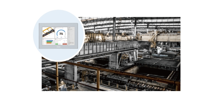
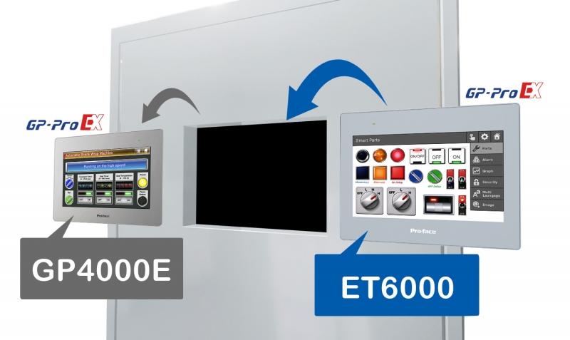
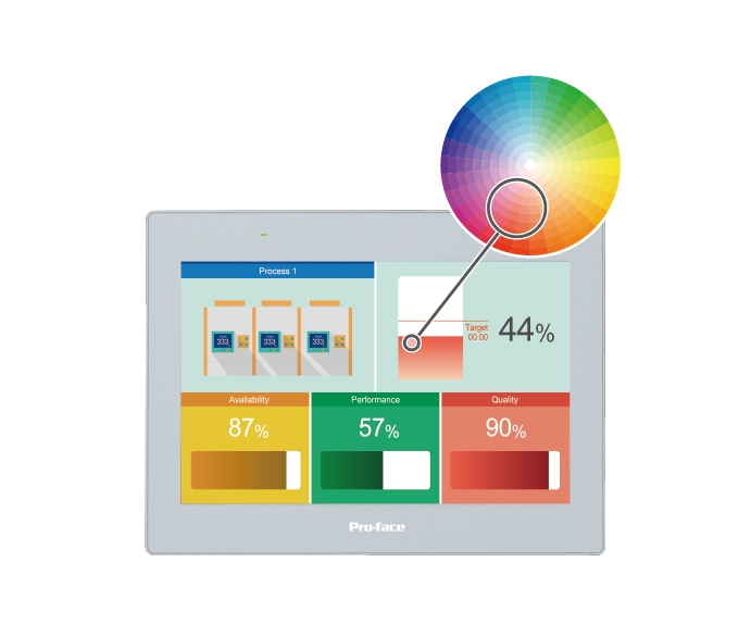
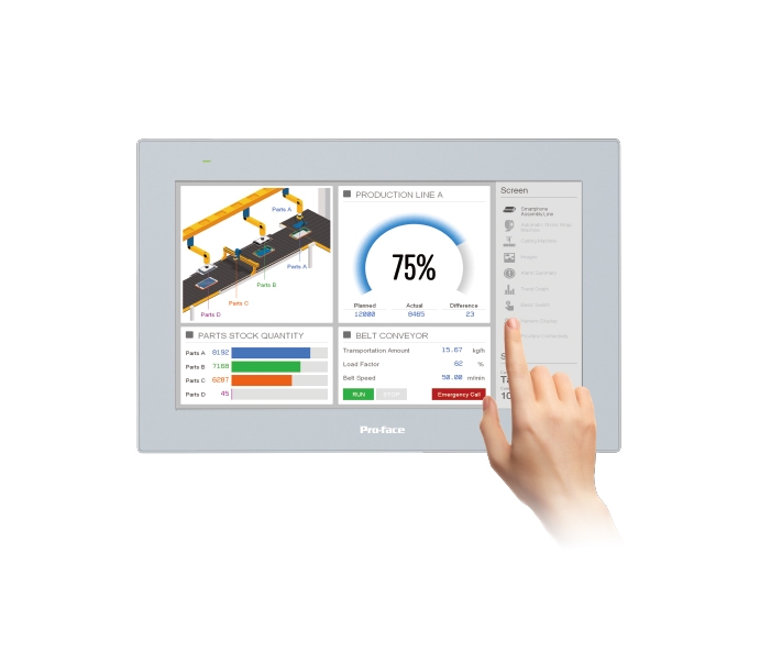
ET6000 Series has cost-effective and has just enough functionality. And easy migration with software and hardware compatibility. Enhance your machine with features and good performance from HMI Centric concept.


 15” wide (1,366 x 768)

.jpg)