 |
|
Calibration Gauge/Gauge Pin Unit/Fixture Guide for Surface Variation Detectors
|
|
Calibration Gauge |
|
Gauge outside dia.(mm) |
Gauge pin Unit |
Accuracy |
|
Φ1.0 |
TMG-10 |
±1μm |
|
Φ0.5 |
TMG-05 |
±1μm |
|
|
[ *] Φ0.5mm or less can be made for Φ0.1mm.
|
|
Gauge pin Unit Fixture and Gauge pin Unit |
|
Model |
Use for gauge pin Unit |
Model of
Gauge pin Unit Fixture |
|
TM-1000S |
TMG-05 |
01 |
|
TM-1003 |
TMG-05 |
02 |
|
TM-1000XY |
TMG-05 |
03 |
|
TM-1004 |
TMG-05 |
04 |
|
|
|
|
|
TM-1100XY |
TMG-05 |
05B |
|
TM-1003W |
TMG-05 |
06B |
|
TM-1104W/TMS-1104W |
TMG-05 |
07B |
|
|
|
|
|
TM-503W |
TMG-01 |
16B |
|
|
|
|
|
TM-3001W |
TMG-10 |
08B |
|
TM-3002W |
TMG-10 |
09 |
|
TM-3004W |
TMG-10 |
10B |
|
TM-3008W |
TMG-10 |
10B |
|
TM-3016W |
TMG-10 |
10B |
|
|
|
|
|
TM-4001/4001W |
TMG-10 |
---- |
|
TM-4002 |
TMG-10 |
12B |
|
TM-4002W |
TMG-10 |
17 |
|
TM-4004 |
TMG-10 |
13B |
|
TM-4008 |
TMG-10 |
13B |
|
TM-4016 |
TMG-10 |
13B |
|
|
|
|
|
TM-6004 |
TMG-10 |
14B |
|
TM-6008 |
TMG-10 |
14B |
|
TM-6016 |
TMG-10 |
14B |
|
|
|
|
|
TM-7003 |
TMG-10 |
15B |
|
TM-7009 |
TMG-10 |
15B |
|
TM-7012 |
TMG-10 |
15B |
|
|
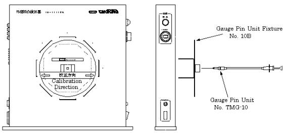
Example of calibration method (TM-3004W)
The detector is provided a calibration before the delivery. However, if another calibration is required in order to assume the detecting sensitivity at the examination, you have to follow the method mentioned below to make it correctly, using a calibration gauge pin unit. (Calibration Gauge Pin Unit No.TMG-10 and Gauge Pin Unit Fixture No.10B are the optioned items).
**Be sure to warm up the detector for 10 minutes and clean the glass filter of the emitter and the receiver before calibration.
Calibration procedure for #1 axis.
1. Place the Gauge Pin Unit Fixture into the Detector with "arrow" mark setting to the #1 axis. (ref. Fig.).
2. Set Variation Detecting Level Setter at "1.00".
3. Insert the point of Gauge Pin Unit into the center of detecting area smoothly and quickly but in the horizontal manner against the detecting area.
4. While repeating the insertion, adjust #1 axis Gain Adjustment VR at the minimum level where the variation detection alarm lamp turns on at the time when the Gauge Pin Unit is inserted. Variation Detection Alarm Lamp turns on at the time when the point of Gauge Pin Unit is inserted.
*The Variation Detection Alarm Lamp would turn on occasionally when the point of Gauge Pin Unit is pulled out, but this phenomenon shall be ignored.
*While repeating the insertion, take interval of 3 seconds after Variation Detection Alarm Lamp turns off.
*Sensitivity comes up by turning Gain Adjustment VR clockwise and comes down by turning it anti-clockwise.
5. Set Variation Detecting Level Setter at "1.03".
6. Repeat the insertion and adjust #1 axis Gain Adjustment VR at the level where Variation Detection Alarm Lamp does not turn on at the time when the point of Gauge Pin Unit is inserted.
7. Repeat the procedure (2) through (6). And, the calibration has been finished properly if Variation Detection Alarm Lamp turns on at the level "1.00" and turns off at the level "1.03".
Follow the above procedure to calibrate other axes, placing Gauge Pin Unit Fixture into the Detector with "arrow" mark setting to the axis to be calibrated.
|
 |
|
|
|
|
|
|
|
|
|
LDM-PCEX2 - Laser Diameter Measurement System
|
|
LDM-PCEX2 is a software application that takes the result measured using Takikawa's laser diameter from the display part into the PC by serial communications (RS-232C), and to file the graph print and the measurement result
Encoder system unit (option)
This unit greatly enhances the function of the LDM-PCEX2:
・ Start/Stop of measurement data recording can be done by external switch , output , reading of a rotarly encorder.
・This has USB <-> RS-232C converter . Even if PC has no RS-232C , connectable by USB cable.
Quality Control Application
The application reads the data acquired by LDM-PCEX2 and creates a quality control valiue and various graphs. The process variation.of the products can be grasped and can be judged objectively with a quality control index.
|
|
SPECIFICATIONS
|
|
Model |
LDM-PCEX2 |
|
PC/OS to be used |
Meet the forrowing requirement. |
|
IBM PC compatible (DOS/V machine): CD-ROM should be able to be used.
USB port or a parallel port is installed in the main body, and operate.
|
|
Microsoft Wndows Vista(checked by 32bit type), 7 (32bit/64bit) , 8 (64bit) ,8.1(64bit)
*(Checked only Japanese Version)
|
|
Corresponding Model |
Connected by TAKIKAWA's LASER DIAMETER |
|
Communication Rate |
An initial value is 9600bps. |
|
Data Bit Length |
8bits |
|
Stop Bit Length |
1bit |
|
Parity Bit |
None |
|
Function |
Measurement Value Display, Peak value display, Measurement value state display
Data writing , Graph Drawing and printing function.
|
|
Store file format |
CSV style(text file) |
|
|
Type |
Encorder system unit (Option) |
|
Max. clock frequency |
2kpps |
|
Count sensor power supply |
DC+12V Max80mA |
|
Relay contact("a" contact, AC250V Resistance load 2A) |
|
Monitor output |
|
Communication |
PC side: USB B type LDM display side: RS-232C |
|
Power supply |
AC100 - 240V Free power supply 50/60Hz, 3VA or less |
|
Ambient condition |
Temperature:0 - 45 degree centigrage,
Humidity:35 - 85%RH(No condensation) |
|
Weight |
Estimated: 470g
|
|
Outside dimention |
140(W) * 60(H) * 100(D)[mm] |
|
|
|
Quality control application |
|
Measurement Display |
Displays acguired measurement data as graph:
-
Displays all maximum/minimum in every section in display.
-
The average value plot of each section
|
|
Histogram |
It is possible to see the variation state of measured value visually. |
|
Quality Control Index |
Calculated values, such as the maximum/minimum, an average / standard deviation value, distribution/deviation, and a process capability index (Cp/Cpk), are displayed. |
|
Graph display |
Selection is arbitrarily possible in display ch selection convenient to print or a plot color. |
|
|
|
|
* In Windows vista,7, 8, 8.1 the company name and the product name that has been described to Microsoft Corporation and other this papers are the registered trademarks or trademarks of each company.
* The specification is a previous notice and might change.
Example of screen under measurement when LDM-110EX is used
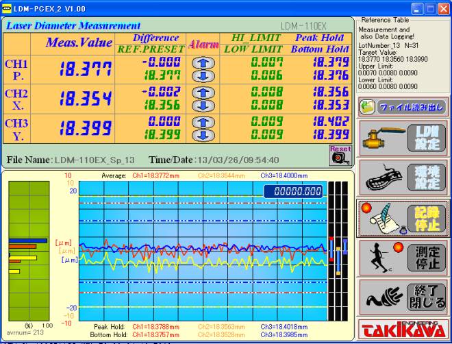
Example of screen of making it draw to simultaneous 3 channels in graph
|
|
|
|
Example of the use of an encoder system unit
・The ability to count pulses from the rotary encoder is added by using an optional encoder system unit. The horizontal axis of the graph generally is time display, by using this option, it is possible to display the horizontal axis of the graph distance is possible.
RS232C port is also provided together can also be connected to the LDM display unit.
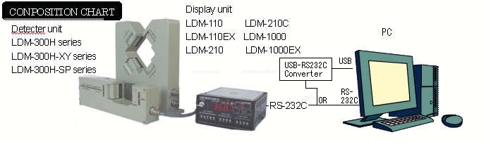
Constitution
Connected as shown below each device and the encoder system unit.
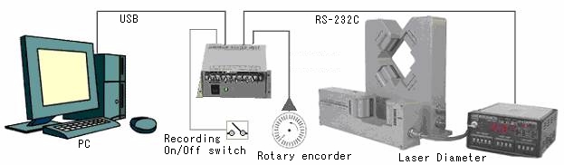
・Rotary encorder and recording On/Off switch can be connected in accordance with the needs of customers.
|
|
|
|
|
|
|
|
|
|
Please read before using the printer
*The mechanisms in printers are consumables. Even within the warranty period, please note that certain cases are not covered.
* Precautions
-
・Please do not because the printing in the state that does not put the paper may cause a malfunction.
-
・Please use the always FEED switch when the paper feed. Pull the paper without the FEED switch and may cause a malfunction.
-
・Please do not drop or hit the printer.
-
・Be decomposed by yourself, be repaired, please do not absolutely.
-
・Please not wet a printer.
-
・Please do not use it to remove the panel.
-
・When you pull in reverse printing paper from the pledged opening, please do not it will be cause of failure.
-
・When the printer to is wrong ( When it is smoke or a strange sound or smell ), immediately turn off the power, make sure that the abnormality is not continuing.
* Attention of the handling of the thermal paper:
・Thermal paper is a special paper which surface has been specially treated with chemicals and it is to be black by thermal chemical reaction.
-
・Please save it in the dry cool and dark spece.
-
・Please do not scrape the hard thing, do not place near organic solvents.
-
・Do not touch a long time to vinyl chloride film, eraser and adhesive tape.
-
・Do not overlap the diazo and wet copy immediately after copying.
-
・Do not use chemical glue when gluing.
-
・Heat-sensitive paper by adhesive tape might be discolored. Be sure to stick the back
with double-sided tape or the like.
-
・When you touch by hand that in sweaty, there is that blurred the record or fingerprint.
-
・Please use the specified thermal paper.
* Installation
-
・Installation of printer please use between from the horizontal to the vertical.
-
・Use or storage in the following places, it will be cause of failure.
・Do not install.
・ A place with much mine dust and strong vibration.
・ The place of electromagnetic noise and occurrence of corrosive gas.
・ The place where is exposed to derect sun, or where there is a lot of moisture and oil.
・ The place where the temperature is more than 40℃ and less than 0℃ of place.
・ The place where relative humidity is more than 80%.
・ The place where you can have sudden temperature change and consider dew condensation.
|
|
|
|
|
|
|
|
|
|
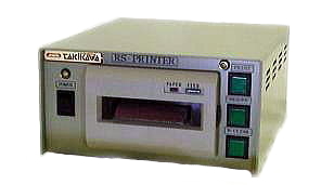
RS-Printer - Printer for Laser Diameter
|
|
|
|
|
RS-PRINTER takes through the RS-232C interface and prints the display value from Takikawa’s Laser Diameter. The LDM-PCEX2 software collates the results and transfers the results to a PC through RS-232C. |
|
SPECIFICATIONS
|
|
Type |
Printer for LASER DIAMETER |
|
Model |
RS-PRINTER |
|
Printer |
Thermal type, 20 digit, 58mm wide |
|
Corresponding model |
Connected by TAKIKAWA's LASER DIAMETER
LDM-110、110EX、210、210C、1000、1000EX
|
|
Communication rate |
Difference depending on the model. An initial value is 9600bps. |
|
Power supply |
AC100 - 240V Free power supply 50/60Hz, less than 8VA |
|
Outside dimention |
180(W)×90(H)×210(D)[mm] |
|
Ambient condition |
Temperature:0 - 45 degree centigrage, Humidity:35 - 85%RH(No condensation)
|
|
|
*Please read before using the printer |
|
|
|
|
|
|
|
|
|
LDM-100QC - Quality Control Printer
|
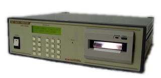 |
A unit to print out statistical calculating value necessary to quality control such as average, standard deviation, histogram, etc.
Click here (LDM-PCEX2)
|
|
SPECIFICATIONS |
|
Model |
LDM-100QC |
|
Input |
BCD data input
(RS-232C or Analog deviation voltage is also available by option.) |
|
Setting items |
Center value, Upper value, Sampling method, Sampling period,
No. of data, Histogram width, Date |
|
Battery back-up |
|
Printer |
Thermal type. 27-digit. 58mm wide |
|
Print out contents
|
Each set item, T-graph(Real time), Histogram, No. of data, Max. value, Min. value, Range, Average, Standard deviation, Variance, Deviation, Process capability index, Bias for specification |
|
Display |
20 digits * 2 lines LCD with Back light |
|
External input |
Start/Stop, Hold(Trigger) |
|
Power supply |
AC100 - 240V Free power supply 50/60Hz, less than 10VA |
|
Outside dimension |
350(W) * 99(H) * 331(D)[mm] |
|
Weight |
3.5kg |
|
Accessory cable |
BCD cable 1pcs. |
|
Ambient condition |
Temperature: 0 - 45 degree centigrade, Humidity:35 - 85%RH(No condensation) |
|
|
* Please read before using the printer |
|
|
|
|
|