LED ON / OFF control, adjustable screen saver activation time
Brightness adjustment
16 levels of adjustment available via touch panel in the configuration menu
Language Fonts *1
Japanese, ASCII, Chinese (Simplified), Chinese (Traditional), Korean, Cyrillic, Thai
Character sizes
8 x 8, 8 x 16, 16 x 16 and 32 x 32 pixel fonts
Font sizes
Width can be expanded 1 to 8 times. Height can be expanded 1/2 and 1 to 8 times.
8 x 8 pixels
40 characters per row x 30 rows
8 x 16 pixels
40 characters per row x 15 rows
16 x 16 pixels
20 characters per row x 15 rows
32 x 32 pixels
10 characters per row x 7 rows
Memory
Application Memory
When using GP-Pro EX:
Media: FLASH EPROM
Screen Area *2: 16MB
User Font Area: 8MB
Logic Program Area: 132KB
*3(Equivalent to 15,000 steps)
Free Space: None
Removable System: None
Backup Memory
When using GP-Pro EX:
Screen Area: nvSRAM 128KB
Variable Area: nvSRAM 64KB
Battery: Memory / Primary battery for clock data backup (Send back for replacement)
Touch Panel
Type
Resistive Film (analog)
Lifetime
1 million touches or more
Interface
Serial (COM1)
RS-232C/RS485 x 1
RS-232C (Connector type: RJ45, Isolation: None, Maximum baud rate: 115,200 bps, Cable Type: Shielded, Cable Maximum length: 15 m (49 ft), 5 Vdc power supply for RS-232C: None)
RS-485 (Connector type: RJ45, Isolation: None, Maximum baud rate: 115,200 bps, Cable Type: Shielded, Cable Maximum length: 200 m (656 ft), Polarization: Setting is required via software when connecting Multiple LTs. Refer to the "GP-Pro EX Device/ PLC Manual" for the setting. 5 Vdc power supply for RS-485: None) *4
CANopen (Master)
CAN-CiA (ISO 11898-2:2002 Part 2), Connector: D-sub9 (pin)
Ethernet
IEEE802.3 compliant Ethernet x 1
(Connector type: RJ45, Driver: 10 M half duplex (auto negotiation)/ 100 M full duplex (auto negotiation), Cable type: Shielded, Automatic cross-over detection: Yes)
USB (Type A)
USB 2.0 (Type A) x 1
(Power Supply Voltage: 5Vdc +/-5%, Maximum Current Supplied: 500mA, Maximum Transmission Distance: 5m (16.4 ft.))
USB (Mini-B)
USB 2.0 (Mini-B) x 1
Control
DIO (Sink Type)
20 Points Standard Input (including 2 Points for Fast Input)
10 Points Standard Output, 2 Points for Fast Output
*2Use the screen area when the user font area's capacity is exceeded - for example, when an image font or a picture font is used.
*3Up to 60,000 steps can be converted in software. However, this reduces application memory capacity (for screen data) by 1 MB.
*42-wire connection is available for RS-485. When a Device/PLC supports 2-wire connection, 4 wires (RXD+, TXD+, RXD-, and TXD-) can be short-circuited to be 2 wires (RXD+ and TXD+ = D1, RXD- and TXD- = D0). For details on the connection, refer to the connection manual.
General Specifications
International Safety Standards
Rated Input Voltage
24 Vdc
Input Voltage Limits
20 to 28.8 Vd
Acceptable Voltage Drop
10 ms or less at 20.4 Vdc
Power Consumption
10 W or less
In-Rush Current
30 A or less at 28.8 Vdc
Voltage Endurance between power terminal and frame ground (FG)
500 Vdc for 1 minute
Insulation Resistance between power terminal and FG
10 MΩ or higher at 500 Vdc
Environmental Specifications
Standard compliance
IEC 61131-2
Ambient operating temperature for the display and the rear module
Horizontal installation
0 to 50°C (32 to 122°F)
Vertical installation
0 to 40°C (32 to 104°F)
Storage temperature
- 20 to 60°C (- 4 to 140°F)
Storage altitude
0 to 10,000 m (0 to 32,808 ft)
Operating altitude
0 to 2,000 m (0 to 6,560 ft)
Surrounding Air and Strage Humidity
5 to 85% w/o condensation (non-condensing, wet bulb temperature 39°C (102.2°F) or less)
Degree of pollution
IEC60664
2
Degree of protection
IEC61131-2
IP20 with protective covers in place
Corrosive gases
Free of corrosive gases
Dust
≤0.1 mg/m3 (10-7 oz/ft3) (non-conductive levels)
Atmospheric pressure (Operating Altitude)
800 to 1,114 hPa (2000 m (6,561 ft) or lower)
Vibration resistance
Mounted on a DIN rail
3.5 mm (0.138 in.) fixed amplitude from 5 to 8.4 Hz
9.8 m/s2 (1 gn) fixed acceleration from 8.4 to 150 Hz
Mounted on a panel
3.5 mm (0.138 in.) fixed amplitude from 5 to 8.6 Hz
9.8 m/s2 (1 gn) fixed acceleration from 8.6 to 150 Hz
Mechanical shock resistance
Mounted on a DIN rail
147 m/s2 (15 gn) for a duration of 11 ms
Mounted on a panel
147 m/s2 (15 gn) for a duration of 6 ms
Electrostatic discharge
IEC/EN 61000-4-2
8 kV (air discharge)
6 kV (contact discharge)
Rediated radio frequency electromagnetic fields
IEC/EN 61000-4-3
10 V/m (80 MHz to 3 GHz)
Fast transients / Burst noise
IEC/EN 61000-4-4
Power lines: 2 kV
Digital I/O: 1 kV
Relay outputs: 2 kV
Ethernet line: 1 kV
COM line: 1 kV
CAN line: 1 kV
Surge immunity
IEC/EN 61000-4-5
Power supply: CM: 1 kV; DM: 0.5 kV
Digital I/O: CM: 1 kV; DM: 0.5 kV
Shielded cable: 1 kV
CM = common drive
DM = differential drive
Conducted disturbances induced by radio-frequency fields
IEC/EN 61000-4-6
10 Veff (0.15 to 80 MHz)
Mains terminal dusturbance voltage
EN 55011 (IEC/CISPR11)
150 to 500 kHz, quasi peak 79 dBμV
500 kHz to 30 MHz, quasi peak 73 dBμV
Electric field strength
EN 55011 (IEC/CISPR11)
30 to 230 MHz, quasi peak 10 m @40 dBμV/m
230 MHz to 1 GHz, quasi peak 10 m @47 dBμV/m
Vibration immunity (operating)
IEC 61131-2
Protection structure
NEMA TYPE 4X (indoors, with panel embedded)
Protection (front module)
IP65f - (IEC 60529)
Protection (rear module)
IP 20 - (IEC 60529)
Shock immunity (operating)
IEC 61131-2
15 gn 11 ms
Cooling method
Natural air circulation
Weight
749 g (26.41 oz)
Color
Front module: PT404 Rear module: RAL 7032
Material
Front module: PAA+GF
Rear module: PC/PBT
Digital Inputs
Digital Input Characteristics
Rated Current
5 mA
Inrush Values
Voltage
30 Vdc
Current
6.29 mA max.
Input impedance
4.9 kΩ
Input type
Sink/Source
Rated voltage
24 Vdc
Maximum Allowable Voltage
28.8 Vdc
Input limit values
ON Voltage
15 Vdc or more (15 to 28.8 Vdc)
OFF Voltage
5 Vdc or less (0 to 5 Vdc)
ON Current
2.5 mA or more
OFF Current
1.0 mA or less
Isolation
Method
Photo coupler Isolation
Between internal logic
500 Vdc
Filtering
0.5 ms x N (N is 0 to 63)
IEC61131-2 edition 3 type
Type 1
Compatibility
Supports 2 wire and 3 wire sensors
Cable type and length
Shielded: Maximum 100 m (328 ft)
Non-shielded: 50 m (164 ft)
Terminal blocks
Type: 3.5 mm (0.137 in.) pitch
Terminal blocks are removable
Input paralleling
No
* I0 and I1 are Fast input terminals and can be also used as a Standard input. For specifications, see the specifications of Fast Input.
High Speed Counter Input Characteristics
Rated Current
Voltage
24 Vdc
Current
7.83 mA
Inrush values
Voltage
30 Vdc
Current
9.99 mA
Input impedance
3.2 kΩ
Input type
Sink/Source
Rated voltage
24 Vdc
Maximum Allowable Voltage
28.8 Vdc
Input limit values
ON Voltage
15 Vdc or more
OFF Voltage
5 Vdc or less
ON Current
5 mA or more
OFF Current
1.5 mA or less
Isolation
Method
Photo coupler Isolation
Between channels logic
500 Vdc
Filtering
None, 4 μs, 40 μs
IEC61131-2 edition 3 type
Type 1
Compatibility
Supports 2 wire and 3 wire sensors
Cable
Type
Shielded
Length
Maximum 10 m (33 ft)
Terminal blocks
Type: 3.5 mm (0.137 in.) pitch
Terminal blocks are removable
Maximum frequency
· 100 kHz is the maximum frequency for Single-phase
· 50 kHz is the maximum frequency for 2-phase
· Duty Rate: 45 to 55%
(1) When connecting as power surges * To use 3.0A common current, connect to A3 and A4 for V1+. (B3 and B4 for V1-)
Caution: Q0 and Q1 circuits are push-pull circuits. The following is the operation of the push-pull circuit at the Sink Output and the Source Output.
Sink Output: +24(V) is output to terminal Q0, Q1 when the logic for Q0, Q1 is off
Source Output: 0(V) is output to terminal Q0, Q1 when the logic for Q0, Q1 is off
Standard Output terminals Q2 or later are common open collector outputs.
Do not connect Fast Output terminals Q0, Q1 and Standard Output terminals Q2 or later. It will short.
If you add a manual circuit to terminal Q0, Q1, isolate the manual circuit and terminal Q0, Q1 with a relay. Without isolation, it will short.
Between power supply port and protective earth ground (PE) = 500 Vdc
10 MΩ or more
Residual voltage
for I = 0, 1 A
1.5 Vdc or less
Delay
Off to on (50 mA load): 1.1ms
On to off (50 mA load): 1.1ms
NOTE: The delay is not including the cable delay.
Minimum load impedance
80 Ω
Maximum Pulse output frequency
50 KHz
Maximum PWM output frequency
65 kHz
Accuracy Pulse Output/ PWM Output
Frequency
Accuracy
Duty
10 to 100 Hz
0.1%
0 to 100%
10 to 1000 Hz
1%
1 to 99%
1.001 to 20 kHz
5%
5 to 95%
20.001 to 45 kHz
10%
10 to 90%
45.001 to 65 kHz
15%
15 to 85%
Duty rate range
1 to 99%
Cable
Type
Shielded, including 24 Vdc power supply
Length
Maximum 5 m (16 ft)
Terminal blocks
Type: 3.5 mm (0.137 in.) pitch
Terminal blocks are removable
NOTE: When using the acceleration/deceleration pulse output, there is a 1% maximum error for the frequency.
Caution: Q0 and Q1 circuits are push-pull circuits. The following is the operation of the push-pull circuit at the Sink Output and the Source Output.
Sink Output: +24(V) is output to terminal Q0, Q1 when the logic for Q0, Q1 is off
Source Output: 0(V) is output to terminal Q0, Q1 when the logic for Q0, Q1 is off
Standard Output terminals Q2 or later are common open collector outputs.
Do not connect Fast Output terminals Q0, Q1 and Standard Output terminals Q2 or later. It will short.
If you add a manual circuit to terminal Q0, Q1, isolate the manual circuit and terminal Q0, Q1 with a relay. Without isolation, it will short.
Terminal Blocks
Pin Arrangement
Group
Pin
Signal Name
Group
Pin
Signal Name
Fast Output
A1
V0+
Fast Output
B1
V0-
A2
Q1
B2
Q0
Standard Output
A3
V1+
Standard Output
B3
V1-
A4
V1+
B4
V1-
A5
Q3
B5
Q2
A6
Q5
B6
Q4
Pin Arrangement
Group
Pin
Signal Name
Group
Pin
Signal Name
Standard Output
C1
Q7
Standard Output
D1
Q6
C2
Q9
D2
Q8
C3
Q11
D3
Q10
Fast Input/Standard Input
C4
I0
Fast Input/Standard Input
D4
IC0
C5
I1
Standard Input
D5
I2
Standard Input
C6
I3
D6
IC1
C7
I5
D7
I4
C8
I7
D8
I6
C9
I9
D9
I8
C10
IC2
D10
IC2
C11
I11
D11
I10
C12
I13
D12
I12
C13
I15
D13
I14
C14
I17
D14
I16
C15
I19
D15
I18
External Dimensions
Panel Cut-out
* Without the tee option, the display module supports a rotating torque of 2.5 N•m (22.12 lbin).
The crisp display let you create easy-to-read yet detailed operation screens. The integrated control functionality provides Digital I/O, Analog I/O, and Analog temperature inputs as well as USB, serial, and Ethernet communication ports.
Easily verify and debug projects with GP-Pro EX
GP-Pro EX Simulation is an off-line simulation function which enables verification of screens, logic programs, and program operation without connecting to an HMI.
Easily connect to the production site from the office
Use remote monitoring software, GP-Viewer* or data management software, Pro-Server EX* to easily monitor and control HMI screens on the production site, or distribute instruction data and collect real-time production data.
*Requires separate license.
Pro-face Remote HMI
The natural link between the process and your tablet or smartphone. By adding the APP true mobile operation will be possible without loss of operability. Confirm the cause of an error directly with your mobile device and see if the machine can be put back into operation without going on site.
Pro-Server EX
Collect information of operation progress on a PC via Ethernet network. Download operating instructions, such as recipes, from an office PC to a GP.
*Purchase of a separate license is required.
GP-Viewer EX
The screen of theHMI on the site can be monitored from a PC at a remote location.
*Purchase of a separate license is required.
Searching/sorting alarm and sampling history
Easy ascending/descending sorting and conditional search using symbols such as =, > or < of Alarm Part and Sampling Display.
Analyze problem causes easily with historical trend graphs
GP-Pro EX provides the ability to display error logs in graph form, making it easy to analyze the causes of a problem. Supported features include enlarged/reduced display, auxiliary line display for upper and lower limits, and XY scatter graphs.
Adjustments with COGNEX In-Sight vision system
In combination with a COGNEX In-Sight vision system, the settings can be changed when watching images from the cameras onHMI on site.
*A communication driver supports In-Sight Micro series and In-Sight 5000 series. *You can view video images from up to 3 cameras on a single screen. Up to 16 cameras can be connected to HMI. Display position (X/Y), exposure time, focus, lighting and brightness can be adjusted on HMI.
Alarm Analysis function
When an error occurs, an operator can easily seek and check the condition on-site, just by touching the alarm message to call up various error-related data in chronological order. An alarm analysis screen with timing chart of alarm-related device addresses can be simply configured only through a few steps on GP-Pro EX software for easy troubleshooting, debugging and/or design changes of production equipment to reduce downtime for enhanced productivity.
Sampling Data - Collecting various data during production
Temperature, voltage, and other desired address values can be stored in the GP. Data and times can be confirmed on the sampling display.
Historical Trend Graph - Displaying data in an easy-to-see graph
The change in the collected data over time is displayed in an easy-to-understand form with a graph. The graph can be traced back to see the past data.
Operation Log - Recording the operator's operation
Operations are saved to a log, so you can see who did what, and when. The log can also be used for a trend analysis of erroneous operation of operators.
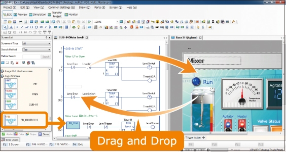
Improving development efficiency and maintaining technical know-how
Screens and logic programs can be edited with the same software, and the same addresses or user-defined control symbols can be shared for both screen parts and logic elements with drag-and-drop operation. Controller addresses can be written directly to help reduce development time.
Using the Function Block feature lets you reuse configured logic components and protect technical know-how via password protection.<br>
Image of Ladder Logic screen. Instruction List Logic screen also available.
*IEC 61131-3-compliant
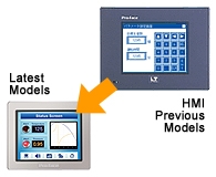
Convert entire projects with Project Converter
GP-Pro EX supports screens made using previous models of LT Series. Data created in GP-Pro/PBIII for Windows or later versions can be converted instantly in Project Converter.
Many pre-configured sample screen for immediate use
A variety of ready-made sample parts are available for download. Sample parts can be used immediately after download, which lets you significantly reduce time spent on screen design.
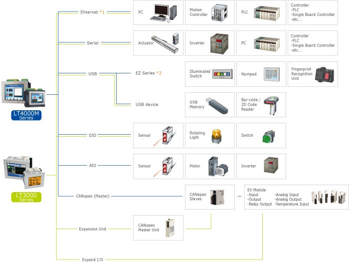
Connect to a wide range of control equipment
Pro-face HMIs support connection with a wide range of industrial controllers including PLCs, motion controllers, robots, and other devices.
*Only for units with Ethernet. *Only for LT4000M Series.
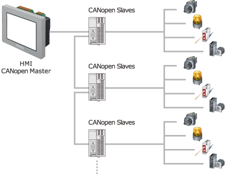
CANopen Networking
The LT4000M provides data exchange with various remote devices via CANopen for an economical and user-friendly system design. Choose between standard I/O modules or more sophisticated products such as motion or control for complex applications.
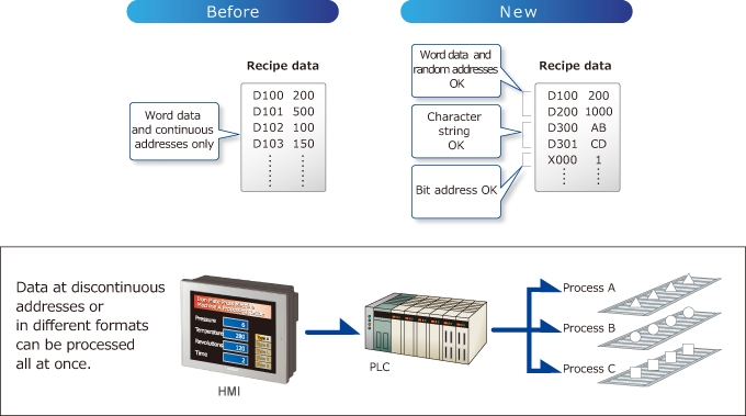
Enhanced Recipe function
With the conventional recipe function, all recipe data must be stored at continuous addresses. The new recipe function allows writing random addresses and multiple data formats as a recipe.
CSV data transfer function
Since the CSV data stored in the USB memory/SD card can be edited, the recipe data can easily be carried for performing updates on-site. The alarm message can be easily changed with CSV files only.
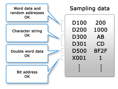
Sampling in different device formats
Text, bits, and variables that could only be set for devices as numeric values can now be mixed. Connected devices + internal addresses can also be set.
Utilize Siemens PLC's tag and improve efficiency
As the tag information of STEP7 Project Files created by Siemens PLC can be imported to GP-Pro EX screen data, you can reduce the man-hours for screen creation.
Tag Import
S7-200 Series
S7-300/400 Series
S7-1200 Series
NO
YES
NO
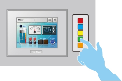
Easy and flexible configuration of lamps and switches
Lamps can be configured in six colors with four lighting states in the screen editor software, GP-Pro EX.
EZ illuminated switches feature easily customizable insert labels.
* For example: HOME, Change Screen, Change, Speed, Run, Stop, Reset, Auto, Manual and etc...
Configuring settings smoothly
When settings need to be configured frequently, the increase in the number of cramped data entry screens to accommodate on-screen numeric keypads and the number of times the operator needs to switch between screens leads to reduced operability and misoperation. Using the EZ Numeric Keypad frees up screen real estate, leading to improved operability. This reduces the stress associated with frequent settings configuration.
Additional features:
Tactile feedback for reliable input operation.
Input numbers and letters even when wearing gloves.
Prevents deterioration of display caused by operation with dirty hands.
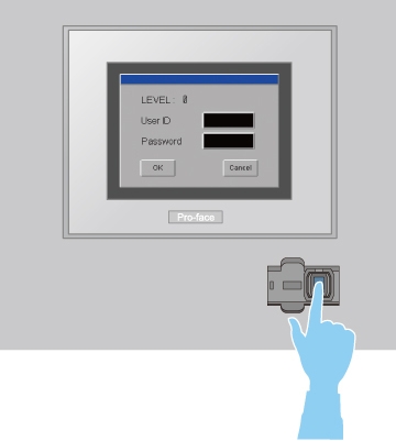
Fingerprint Authentification on HMI Operation
The EZ fingerprint recognition unit can reduce problems or accidents caused by inappropriate password use.
Fingerprint data is registered and maintained through an HMI or PC connected to the fingerprint recognition unit.
* Fingerprint data for up to 100 users can be stored.
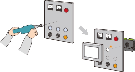
Compact all-in-one unit for easy installation in small spaces
All-in-one design makes it easy to keep equipment compact and allows installation in a φ22 mm hole for easy panel mounting. Easily troubleshoot equipment by replacing the display unit or the control unit.
*Installation in a hole newly opened by a tool or the 22-mm hole used for the switch.
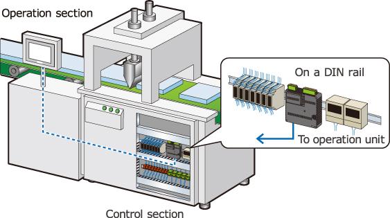
Flexible installation choices for separated or integrated configurations
Use a separation cable* to install the control unit on a DIN rail and the operation unit in a different location. Operation unit is space-saving, and it allows you to install the unit flexibly even though it is difficult to install it due to limitations of space.
*Requires separate 3m or 5m option cable.
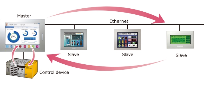
Ethernet Multi-Link function
The Ethernet Multi-Link function allows you to easily add a display unit as a sub-display to the facility without changing any settings of the control device.
Conforms to overseas standards for hassle-free export and use with overseas equipment
UL Hazardous Locations Class I, Division 2 Group A, B, C and D.