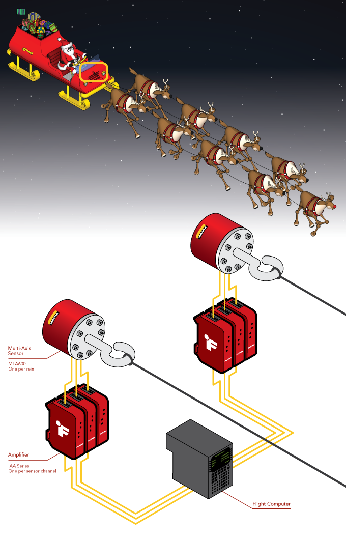
Reindeer Autopilot System
How it Works
- Each reindeer line’s harnesses are each attached to a machined adapter mounted to a FUTEK MTA600 load cell.
- Dasher, Prancer, Comet and Donner are linked to the right hand side tri-axial load cell, while Dancer, Vixen, Cupid, and Blitzen are attached to the left hand side tri-axial load cell. Rudolph, of course, leads the pack and is linked to both lines.
- In flight, as the reigns pull on the reindeer’s harnesses, the load cells measure the thrust forces they generate in response on all three axes.
- The signal generated by the load cells is amplified and sent to the Sleigh Autopilot Navigation Travel Automation (SANTA) System.
- The SANTA system controls the reigns, makes course corrections and monitors the reindeer’s health as the sleigh travels across the sky bringing presents to all the boys and girls of the world.
|
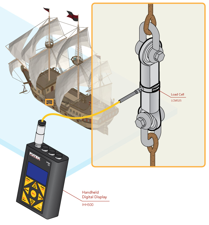
Sailing Ship Rigging Tension
How it Works
- An LCM525 Threaded In Line Load Cell mounts in line on the mast rigging.
- As the rigging is tightened, the IHH500 reads the LCM525’s output and displays it.
- This enables the sailor to see the line tension in real-time as they adjust the rigging.
- By incorporating a TEDS chip into the Binder© plug attached to the LCM525, a single IHH500 can be swapped between sensors without the need to program the IHH500 with the new sensor data.
|
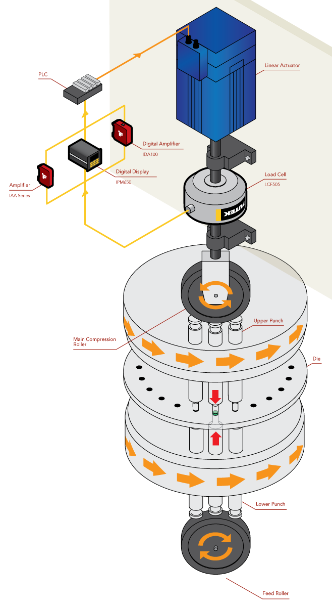
Pill Press Force Verification
How it Works
- A LCF505 Universal Pancake Load Cell with Tension Base is mated between a linear actuator piston and the main feed rooler for the rotary press.
- As the main roller compresses powder into a tablet, the LCF505 measures the compressive force applied to the tablet.
- The measurement from the LCF505 is sent to the digital display (IHH500, IPM650) or displayed on a PC with our SENSIT software(IDA100).
- An amplified analog signal is then sent to the PLC controlling the tablet press enabling the ability to reject faulty tablets and control of the force applied to the tablet.
- Additionally, our SENSIT software can be used to log sensor output for quality control purposes for all three instruments depicted.
|
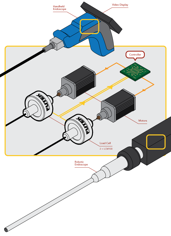
Endoscope Force Control
How it Works
- Two autoclavable load cells are installed in-line with the cables controlling the endoscope's motion.
- As the endoscope is moved, the load cells measure the force required to move the head.
- The force measurement is read by the endoscope's controller allowing it generate the appropriate feedback in the operator's controls.
- The load cells are designed to survive the high pressure, temperature, and PH sterilization environments needed to meet ISO/TC 198 standards and IP69K rating.
- Load cell data captured by instrumentation can then be repurposed to further refine controls and used for traceability requirements.
|
Rotary Shaft Thrust Force
How it Works
- An LTH350 Donut/Through Hole Load Cell is freely slid onto the shaft.
- A pair of thrust bearings and collars secure the donut load cell in place on the shaft.
- A retention bracket is attached to the outer circumference of the sensor, anchoring the sensor to a solid fixture.
- As thrust forces are applied to the shaft, the bearings and collars transmit the load through the sensor for measurement delivering the load to the retention bracket.
- The IHH500 Digital Hand Held Display and the IPM650 Panel Mount Display capture and display the measured load in real time.
- Force data can also be simultaneously captured utilizing the USB220 High-Resolution USB Solution and our SENSIT software on a PC.
|
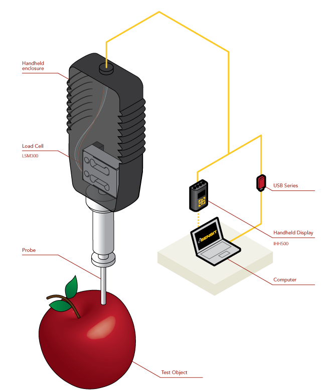
Fruit/Vegetable Penetrometer
How it Works
- An LSM250 or LSM300 OEM Load Cell is mounted inside a handheld unit with a penetrating tip attached.
- An operator then presses the assembly into the flesh of the fruit or vegetable.
- The load cell measures the force applied throughout the entire process which is sent to the IHH500 Digital Hand Held Display or USB220 High Resolution USB Solution connected to a laptop running our SENSIT software.
- The IHH500 and USB220 track the force applied and displays the maximum load that was applied.
- Peak load is then correlated to tables to determine the ripeness of the specimen.
- The LSM250 and LSM300 provide up to 1000% axial overload protection (2.2lb to 25lb) to mitigate operator error.
|
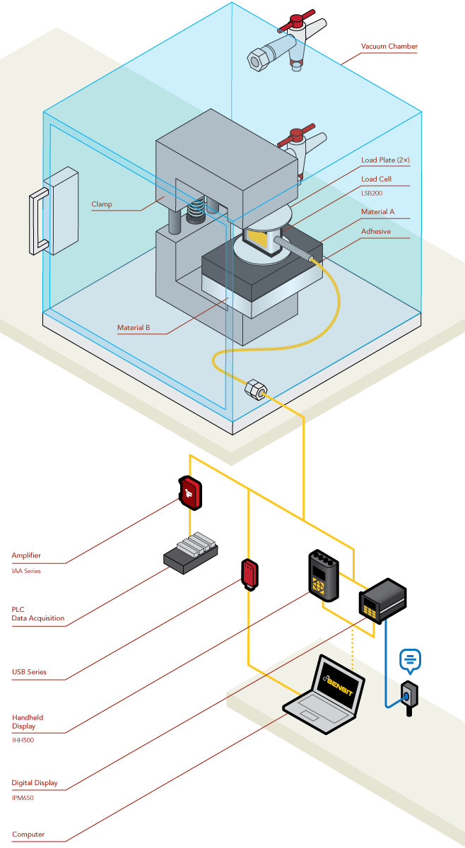
Vacuum Compatible Sensors
How it Works
- In a vacuum environment, outgassing occurs within a material when trapped gasses or material elements boil off or sublimate as pressure falls below normal atmospheric pressures.
- In an ideal case these gasses are removed by the chamber as it maintains the vacuum environment. However, the gasses will more often than not react with the vacuum chamber walls and any hardware inside the vacuum chamber.
- This causes staining and/or corrosion to the material in the chamber. These stains can occlude camera lenses and CCD elements, affect sensor readings, and damage components, often invalidating any measurements taken in the chamber.
- Therefore, it is critical that all components minimize outgassing to protect the integrity of the vacuum environment.
- For FUTEK’s low outgassing sensors, materials such as Teflon cabling and wiring and specialized elements are used to minimize outgassing.
- In this application, a Vacuum Compatible/Low Outgassing LSB200 Miniature S Beam Load Cell is used to measure applied application force over time of two materials being bonded in a vacuum environment.
- The LSB200 is placed inline with clamp holding the two materials together, measuring the force applied.
- The LSB200 cable is routed to the outer wall of the chamber into a bulkhead that helps maintain the vacuum environment and allows the signal to safely exit the chamber.
- The signal is then amplified via an IAA series Analog Amplifier to be sent to a DAQ, displayed by an IPM650 Panel Mount Display, IHH500 Handheld Display, or logged using USB220 USB Output Module on a PC running SENSIT.
|
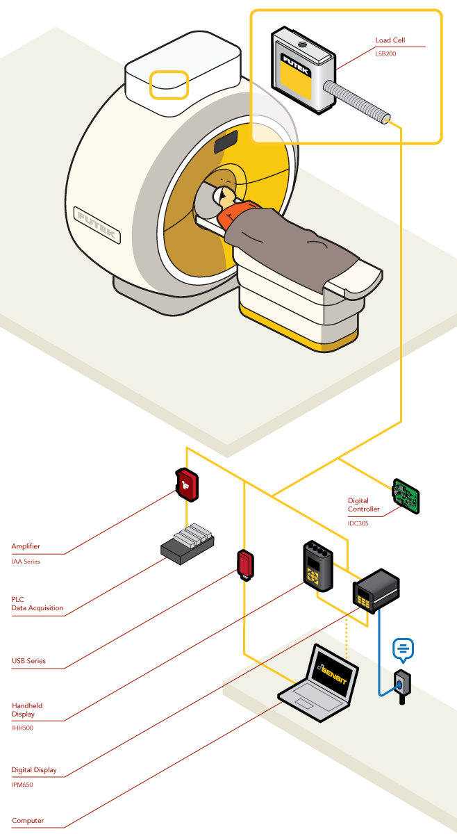
Non-Magnetic Sensors Solutions
How it Works
- Operating within high-strength magnetic fields, requires equipment built from non-magnetic and magnetically shielded materials, such as Beryllium Copper.
- These materials serve two purposes: to prevent the alteration of sensor measurements due to magnetic fields and prevent the sensor itself from being pulled into the source of the magnetic field, damaging equipment.
- Additionally, the use of magnetically shielded materials prevents any fields generate by the sensor to skew measurements made by other sensors and instruments.
- In this application, a non-magnetic LSB200 Miniature S Beam Load Cell is installed within an MRI machine to perform force measurements.
- The LSB200s cabling and signal is routed outside of the MRI to instrumentation a safe distance away from the machine to prevent damage to the MRI and instruments.
- The signal is then amplified via an IAA series Analog Amplifier to be sent to a DAQ, displayed by an IPM650 Panel Mount Display, IHH500 Handheld Display, converted to an SPI signal by an IDC305 Digital Controller, or logged using USB220 USB Output Module on a PC running SENSIT.
|
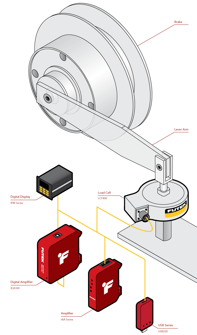
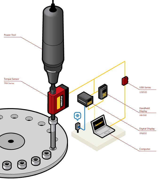
Torque Sensing with Load Cells
How it Works
- A brake has a moment arm attached with a fixed distance to the center of the axis of rotation.
- At the end of the moment arm, an LCF400 load cell is attached to measure the force generated through the arm as the brake generates torque as it resists motion.
- In this scenario, the LCF400 is ideal, since it is highly resistant to extraneous loads and can resistant sudden changes in motor output.
- The signal generated by the LCF400 is then amplified via an IAA series Analog Amplifier to be sent to a DAQ, displayed by an IPM650 Panel Mount Display, or logged using the USB220 USB Output Module on a PC running SENSIT.
- Any force measured by the LCF400 can simply be multiplied by the distance to the center of the motor to derive the torque via the equation: Torque = Force x Distance.
- Force to Torque Conversion can be performed automatically, in real time, using the math function on the included in SENSIT.
- Additionally, the IDA100 Digitally Configurable Amplifier can be used to monitor the torque via the SENSIT software while generating an analog output for closing the loop with a motor controller.
|
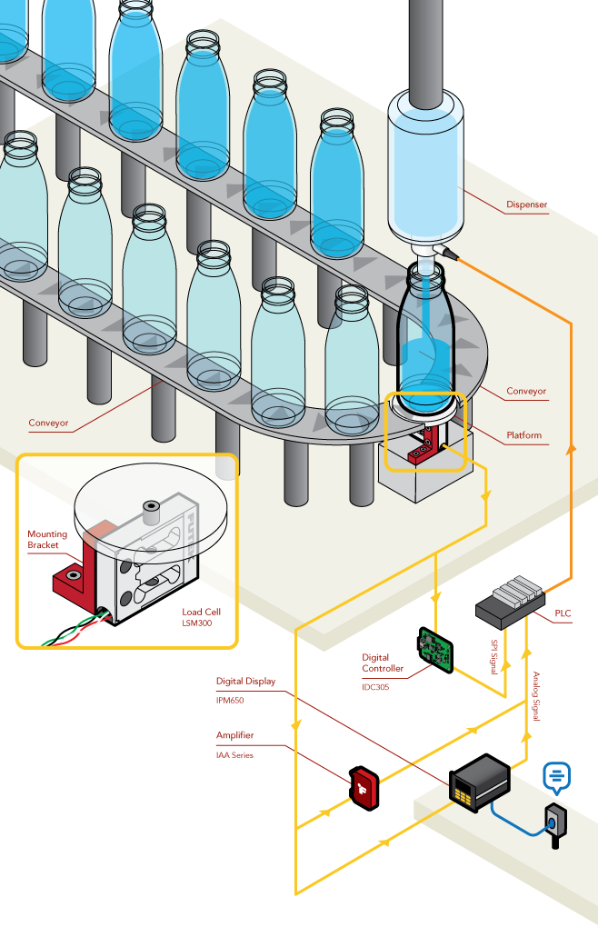
Bottle Dispensing and Weighing
How it Works
- An LSM Series Load Cell is mounted inline below a platform supporting a container being filled.
- As the container is filled, the LSM series sensor weighs the fluid dispensed into the container.
- The weight signal from the LSM series sensor is sent to an IDC305 Digital Controller(SPI signal), IPM650 Digital Display (Amplified Analog Signal), or IAA series Analog Amplifier (Amplified Analog Signal) to convert the signal and send it to a compatible PLC or microcontroller.
- The PLC or microcontroller reads in the signal and shuts off the dispenser when the correct weight of fluid is dispensed.
- In addition to a low non-linearity and non-repeatability, the LSM series sensor exhibits minimal creep and has built-in overload protection to protect the sensor from unforseen accidents.
- Creep is the drift of a load cell’s output when a fixed load is applied. This means that the LSM series sensor is minimally affected by the platform and container weights, maximizing accuracy.
- Lastly, FUTEK offers OEM solutions for the LSM series load cells that offer I2C, RS232, and UART signal outputs.
|