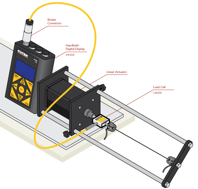
Medical Guidewire Test
How it Works
- Medical guidewire testing systems enables two types of wire tensile testing: destructive and non-destructive.
- During a destructive guidewire tensile test, a guidewire is secured between a prescribed clamp on one end and a clamp on the other. The guidewire is then pulled apart until the specimen breaks.
- During a non-destructive guidewire tensile test, a guidewire is secured between a prescribed clamp on one end and a clamp on the other. The guidewire is then pulled at a controlled rate until a specific force is reached to ensure high reliability and safety of wire.
- FUTEK’s LSB200 Jr. Miniature S-Beam Load Cell is attached in line with the automated clamp to measure the pulling force exerted on the guidewire under test.
- FUTEK's IHH500 can capture and display the peak force right before wire breakage.
|
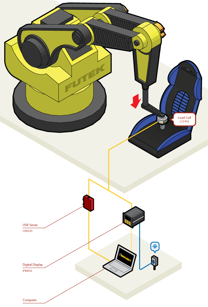
Automotive Seat Durability Testing
How it Works
- Car seats undergo robotic test that repetitively reproduce human movements and loads onto the seat under test.
- FUTEK’s Fatigue Rated Pancake Load Cell LCF456 is fixed to the distal point of the robots arm to quantify the force that is applied in the process with high accuracy and repeatability.
- The load measurements produced help engineers determine the quality of an automotive seat.
- These force measures can be streamed to a computer for analysis utilizing FUTEK’s USB Solutions.
|
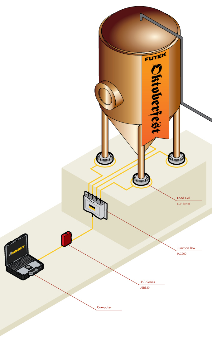
Oktoberfest Fermentation Tank Measurement
How it Works
- In commercial breweries, the contents of fermentation tanks (vessels) need to be accurately gaged throughout it's brewing period. These breweries tend to use load cells at the base of their tanks to monitor these measurements.
- In this depiction, four LCF Family Pancake Load Cells were installed at the base of each of the tank's posts.
- After the fermentation process concludes, the brewers will need to drain the tank to proceed with packaging the beer.
- As this occurs, a carefully siphoned amount of liquid leaves the tank. This measurement is monitored by the LCF load cells and passed to a 2–4 Channel Summing Junction Box (IAC200).
- The summing junction box averages the beer's emptying rate from the tank and streams that to the USB520, which can display the data on a PC.
|
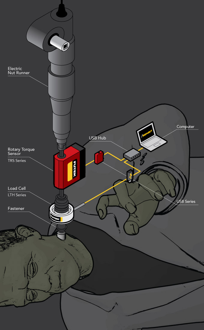
Frankenstein Bolt Fastening Measurement
How it Works
- It would be "off with his head" if Dr. Frankenstein were to let his monster's bolts loosen.
- Not wanting to overshadow the infamous tale of the headless horseman, Dr. Frankenstein used FUTEK's Rotary Torque Sensor to ensure that the torque he applied as he tightened the bolts would withstand the ravages of time.
- Yet, Frankenstein didn't want to over torque the bolts as well. Thus, he incorporated the use for FUTEK's Donut/Thru-Hole Load Cell to fine-tune this procedure.
- His precise measurements for both torque and force were streamed via the blood red USB520 device and the onyx USB220 to be displayed onto his 21st Century Turing Machine.
|
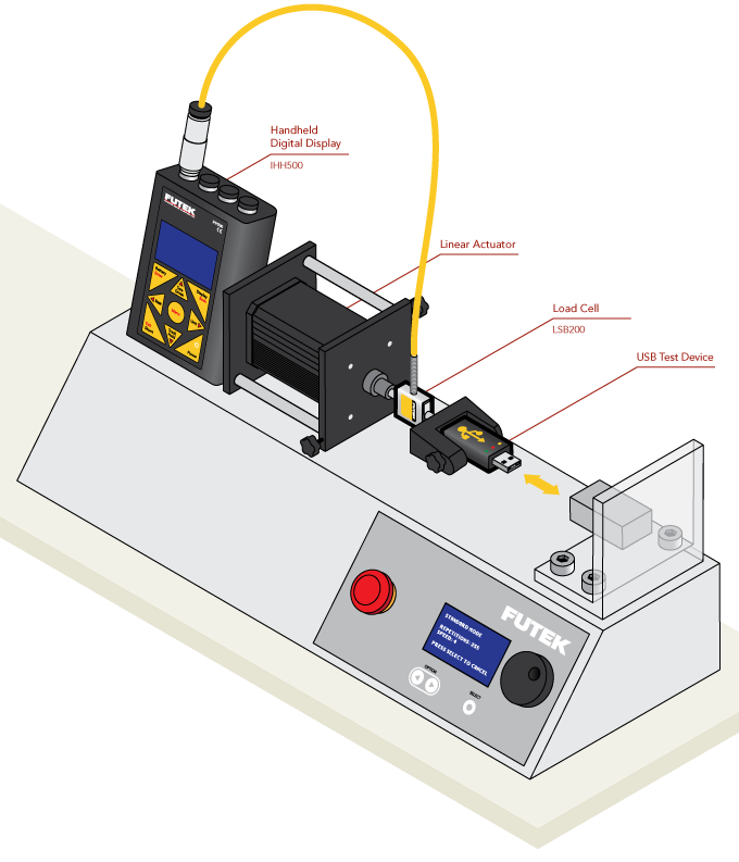
USB Insertion/Extraction Motorized Test
How it Works
- During production, motorized test stands check for durability and insertion force of a USB connector.
- The motorized test stand runs cycle tests on the USB to ensure that the force required to insert or extract the unit from its port meets requirements or doesn't damage the thumb-drive.
- FUTEK’s Jr. S-Beam load cell (either the LSB200 or LRM200) can be fixed onto the horizontal test stand to repeatedly measure the push and pull forces as the USB connector enters and exits the 2.0 or 3.0 port.
- These force measurements can be recorded and reviewed on FUTEK's IHH500 Intelligent Digital Hand Held Display.
|
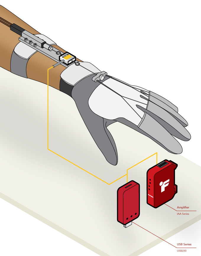
Robotic Glove Rehabilitation Device
How it Works
- The LSB200 Jr. Miniature S-Beam Load Cell is mounted inline of the assistance actuator and tendon wire.
- The LSB200 load cell will measure forces required to do basic tasks for rehabilitation treatments.
- Measurement feedback collected from the LSB200 can be used to diagnose the current status of the patient and track future improvements.
- These measurements can be streamed from the USB220 up to 4,800 samples per second to a PC for data capture and analysis.
- Or the the load cell outputs can be amplified to a PLC with the IAA Series Analog Amplifiers.
|
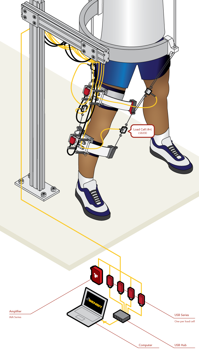
Robotic Leg Rehabilitation Device
How it Works
- The LSB200 Jr. Miniature S-Beam Load Cell is mounted inline of the tension wire.
- The LSB200 load cell will measure tension forces while patient’s legs while walking/moving.
- Measurement feedback collected from the LSB200 can be used to diagnose the current status of the patient and track future improvements.
- These measurements can be streamed from the USB220 up to 4,800 samples per second to a PC for data capture and analysis.
- Or the the load cell outputs can be amplified to a PLC with the IAA Series analog amplifiers.
|
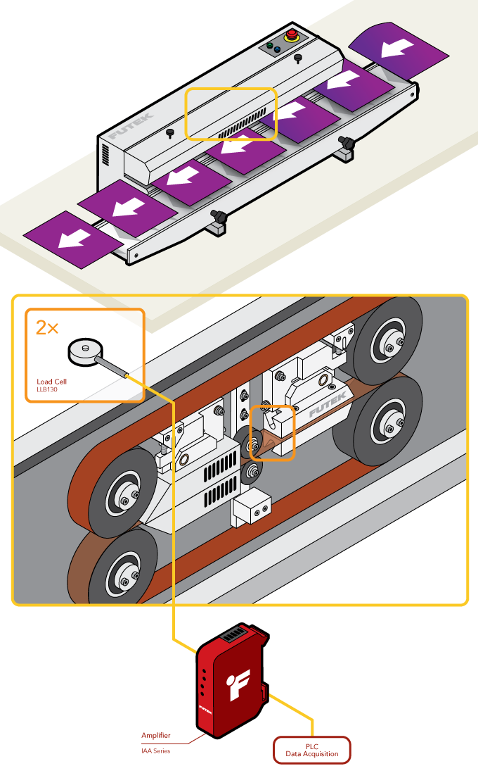
Bag Sealer Validation
How it Works
- In this application, a pair of Miniature Load Buttons is placed so the force exerted on the heater bars by the packaging can be measured.
- As the pouch moves through the heater bars for sealing, the bars are forced outward, resulting in the load cell buttons measuring the applied force.
- Utilizing two load cells ensures that the heater bars are spread apart evenly and functioning correctly mechanically.
- The resulting load cell output is then amplified by the IAA Series Analog Amplifiers for input into the PLC allowing for fault monitoring and pouch seal verification.
|
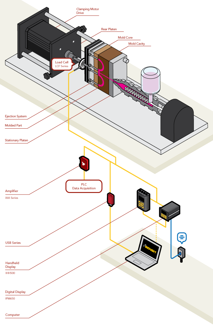
Plastic Injection Molding Force Feedback
How it Works
- LCF Pancake Load Cells are fitted in-line of hydraulic pressure or screw-type clamps measuring the compressive force applied to the mold.
- As the mold expands and contracts due to the molten material, the load cell provides feedback to the PLC with the new compressive force.
- The feedback is used to adjust the clamps in real-time to maintain mold compression.
- When paired with the IAA Series Analog Amplifier, the load cell can provide a variety of amplified outputs such as 0-10 V or 4-20 mA signals for the PLC.
|
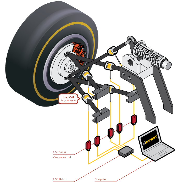
Suspension System Performance Validation
How it Works
- LCM Series or LCB Series load cells are threaded in-line with each suspension arm. It is critical to study the load path and avoid any side load and/or moments.
- As the vehicle is operated on a test stand or driven, the output signal is sent to the USB220 units.
- The USB220 displays and logs the data to a PC via our SENSIT™ software. This data can be used to validate and fine-tune the performance of the suspension system.
|