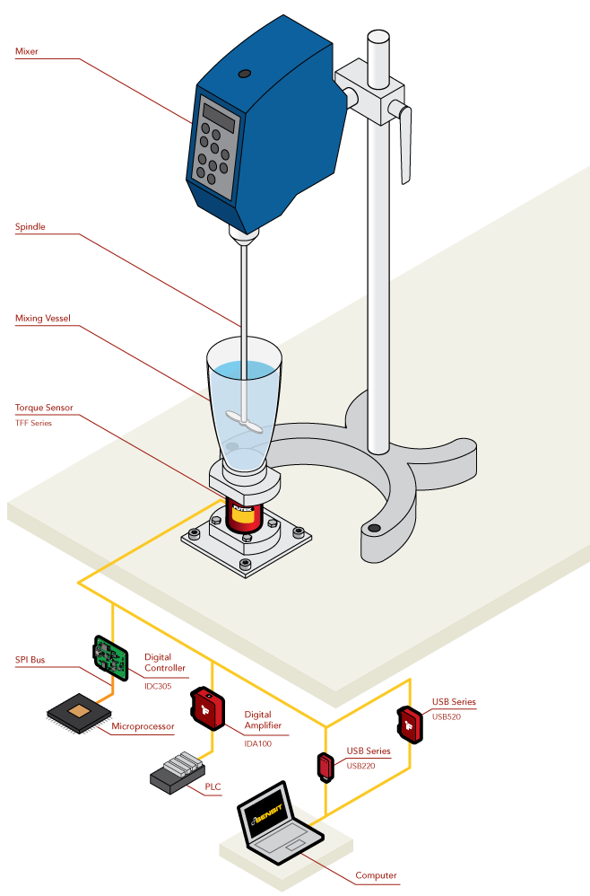
Rheometer Torque Measurement
How it Works:
- A TFF425 Flange-to-Flange Reaction Torque Sensor is mounted beneath a cylinder holding the fluid undergoing analysis by the viscometer.
- A spindle attached to a motor is submerged in the fluid.
- The spindle is brought up to a specific speed and the torque exerted on the cylinder by the spindle is measured with the TFF425.
- The signal from the TFF425 is fed into the IDA100 Amplifier with Digital and Analog Output for amplification and transmission to a PLC.
- For a direct connection to a microprocessor, the IDC305 Digital Controller can be used to send torque sensor data directly via SPI to provide closed loop control.
- Otherwise, the signal from the TFF425 can be captured by the IDA100, USB220, and USB520 High-Resolution USB Solutions and logged with our SENSIT software.
- This data can then be used to meet compliance for ASMT D562, ASTM D1084-16, ISO 3448.
- To measure while coupled to the spindle shaft, the TRS series Shaft-to-Shaft rotary torque sensors can be used.
|
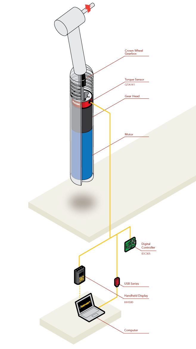
Dental Handpiece Torque Auditing
How it Works:
- A QTA141 Micro Reaction Torque Sensor is installed inline with the handpiece motor and its mount.
- The signal generated by the QTA141 is transmitted to the IHH500 Digital Hand Held Display for display.
- The signal can also be sent to the USB220 High-Resolution USB Solution for display and logging of data on a PC running our SENSIT software.
- Additionally, data logging can be performed with an IHH500 connected to a PC running SENSIT as well.
- Lastly, with the IDC305 Digital Controller with SPI, USB, and Analog Output, the sensor output can be captured via SPI into a microcontroller, USB and a PC running SENSIT, or via Analog Output into a PLC or DAQ.
- Lastly, with the IDC305 Digital Controller with SPI, USB, and Analog Output, the sensor output can be captured via SPI into a microcontroller, USB and a PC running SENSIT, or via Analog Output into a PLC or DAQ.
|
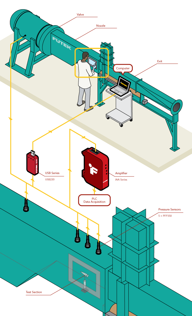
Supersonic Tunnel Pressure
How it Works:
- PFT510 pressure sensors are installed at critical points in the wind tunnel. In this example, sensors are mounted in the pressure tank, throat, and in three locations on the test section.
- As the tunnel runs, the pressure sensors capture data at key points in the tunnel.
- The sensors’ high natural frequency (6 kHz – 100 kHz) allows them to respond to rapidly changing environmental characteristics.
- The output from the sensors is then captured with the USB220 High-Resolution USB Solution and logged on a PC running SENSIT.
- With the live stream of data, SENSIT’s math channel feature can calculate and display the pressure differential or pressure ratio between two sensors.
- Our USB solutions can be integrated with compatible temperature sensors allowing for graphing of pressure versus temperature in SENSIT.
- Alternatively, the sensor's output can be amplified with the IAA Series Analog Amplifiers and captured by a 3rd party DAQ. High bandwidth (50 kHz), ultra low noise, differential amplifiers, such the IAA300, can be used to keep up with these high-speed sensors.
|
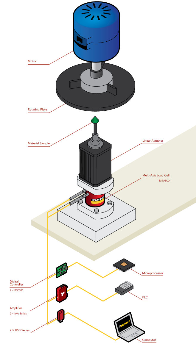
Disc Tribometer
How it Works:
- A material sample is attached to an MBA500 Torque and Thrust Biaxial Sensor paired with a linear actuator.
- A motor spins a disc up to specific RPM.
- The linear actuator then presses the sample into the spinning wheel.
- The MBA500 then captures the applied force and the torque generated by the sample contacting the disc.
- The output from the MBA500 is captured by a pair of USB220 High-Resolution USB Solutions.
- The data from the USB220 is logged on a PC with our SENSIT software.
- For a direct connection to a microprocessor, the IDC305 Digital Controller can be used to send torque and thrust data via SPI.
- Additionally, the IAA series amplifiers can provide either an amplified analog voltage or current signal for a PLC or DAQ.
|
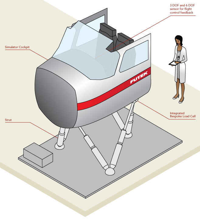
Simulator Force Feedback
How it Works:
- Load cells and torque sensors are integrated directly into the actuators moving the simulator.
- These sensors measure the forces and moments generated by the actuators.
- The sensor’s signals are sent to the control system via analog and digital amplifiers to provide closed loop control feedback and emulate a realistic flight environment.
- Additionally, 3DoF and 6DoF sensors can be incorporated into the pilot controls to provide closed-loop Haptic control in parallel with actuation system.
|
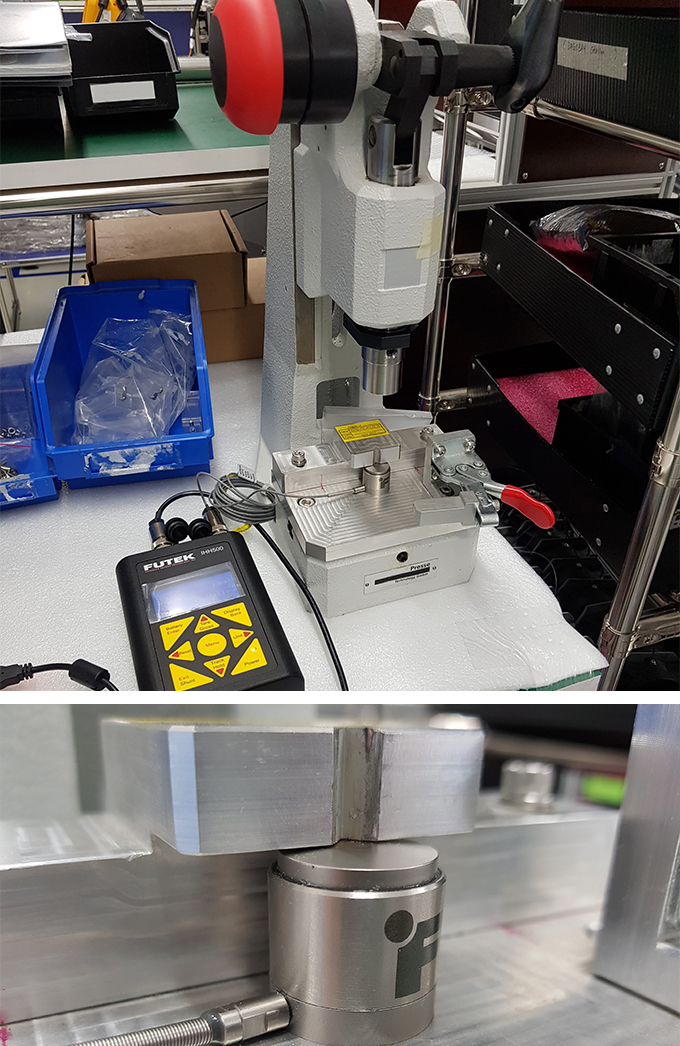
Pin Insertion Force Monitoring
Application: A major player in the industry, one of it is manufacturing plant in Singapore. They wanted to know the force of the insertion of the pin into a fitting. They requested a load cell to be compact and reliable in its measurements. Also to have a large sensing area in order the fitting can be placed on top and the pin be pressed down (inserted). There should be an indication of pass/fail in order to determine the quality of the product.
Solution: Suggested them to use our range of FUTEK due to its high capacity and small in size versions. We suggested them to use the LCA-series (Column load cell) due to a requirement on a larger surface contact point. Paired up together with the IHH500 – Advanced Handheld Indicator in order to get the most accurate readings out. The IHH500 also has the capability to connect to the PC and to use SensIT by FUTEK to do the monitoring and control and data logging.
Outcome: Customer was very satisfied to use our proposal and they are currently using it for multiple stations for quality testing purposes. Customer gave a thumbs up to our mobility of the IHH500 – Robustness of the LCA load cell and the user-friendliness of a powerful software SensIT.
|
Medical Bag Weighing
How it Works:
-
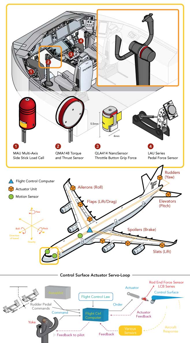
Side Stick: During the product validation phase, MAU300 Gear Shift Load Cell provides quality assurance and flight controls engineers with the appropriate tools to measure the force applied to side stick flight controls. To ensure that this mechanism is operating properly, FUTEK's MAU300 Multi-Axis Gear Shift Load Cell can be installed into the shaft of each flight control side stick.
-
Yoke: Pilots rely heavily on the control column (yoke) to guide the pitch and roll of a plane. By rotating the yoke, the pilot maneuvers on the roll axis. By propelling the yoke forward and backward, that pilot can adjust the elevation and pitch axis. To ensure that the control column is operating properly, quality assurance and flight controls engineers can install FUTEK's MBA500 Torque and Thrust Biaxial Sensor to measure the forces and torques applied the yoke flight control. The MBA500 multi-axis force sensor performs measurements in both the Mz (the roll) and Fz (the pitch) directions.
-
Throttle handle: QLA414 Nanosensor or LMD300 Pinch Force Sensor can be used in the actuation buttons of the throttle handle to measure the pinching or pressing force exerted by the pilot.
-
Pedals: Pedals control the rudder control surface, which can move to the left and right by pushing the corresponding rudder pilot pedal. Utilizing LAU220 pedal force sensors allow engineers to audit the precision of these controls. Utilizing FUTEK's LAU pedal force sensors, quality assurance engineers can measure the force required to operate each rudder pedal flight control as it directs and propels the helicopter through flight.
-
Surface Controls Actuator: During the product design validation, the Control Engineer needs to measure the actuation force being applied to the control surface. This helps to ensure that the necessary force is being exerted and that the control loop is properly calibrated and will operate as expected. LCB Rod End Load Cell is installed between the actuator and the flight control surface to measure the actual actuation force exerted and properly calibrate the actuator servo loop through additional force feedback.
|
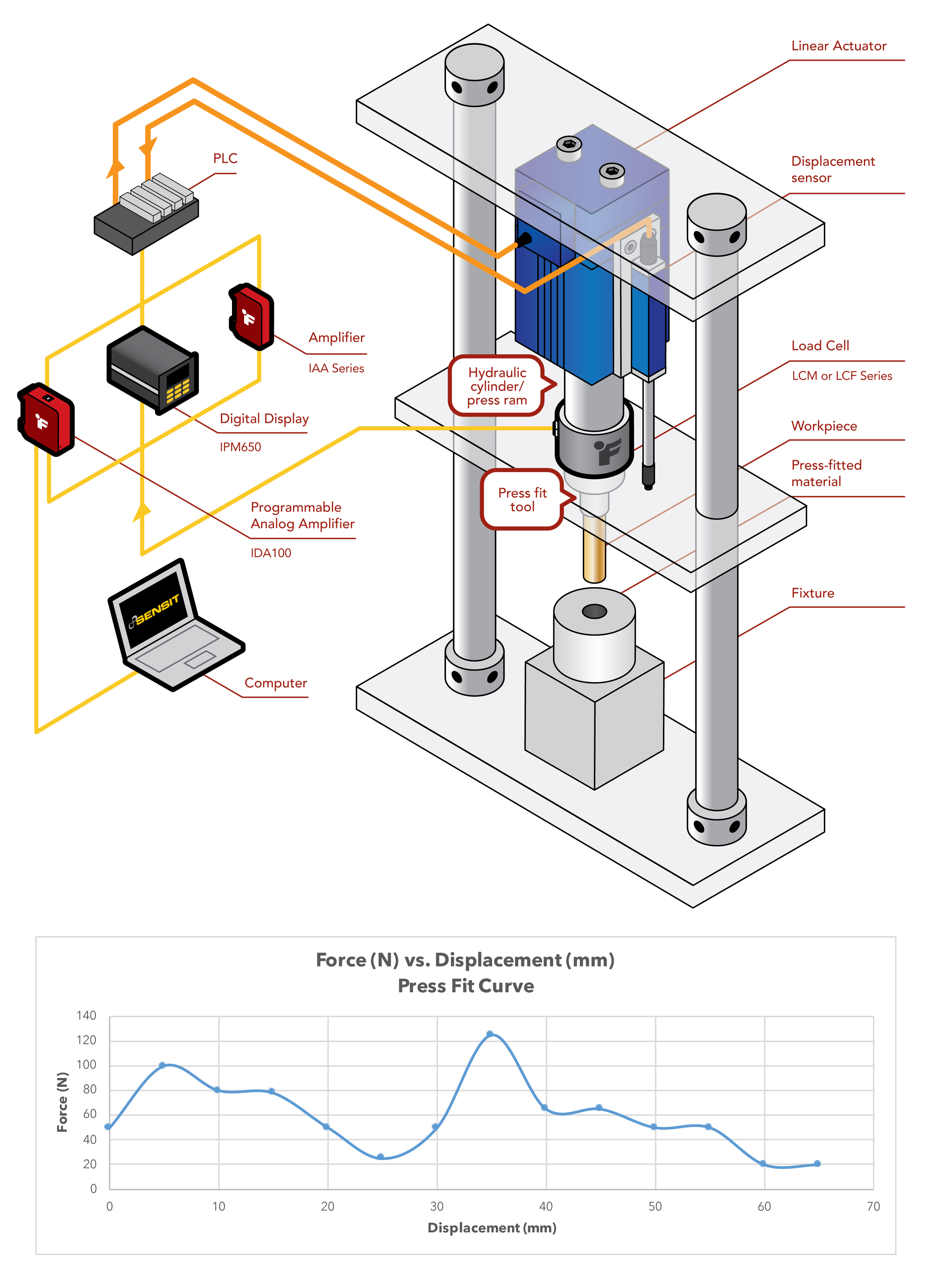
Determining Press Fit Force Assembly
How it Works:
-
A LCF300 Universal Pancake Load Cell is mated between a linear actuator piston and the press fit tool.
-
As the hydraulic or electric cylinder (aka hydraulic ram) press fit the workpiece (i.e. shaft) into the press-fitted material (i.e. hole), the LCF300 measures the press fit force applied.
-
The force measurement signal from the LCF300 is sent to the digital display (IHH500, IPM650) or any of FUTEK signal conditioners (IDA100 or USB520). The signal can also be displayed on a PC with our SENSIT force measurement software.
-
An amplified analog signal can also be sent to the PLC controlling the hydraulic or pneumatic press, enabling the ability to act on defects and quality issues in the press fit assembly in real time.
-
Additionally, SENSIT software can be used to log sensor output for quality control purposes.
|