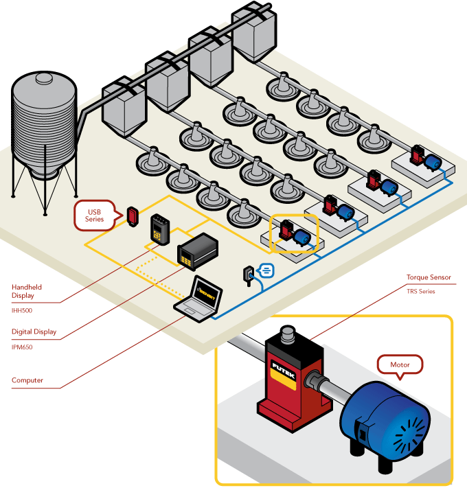
Agricultural Poultry Feeder
How it Works
- FUTEK's TRS Series is an effective tool for motor testing/auditing, feedback control, monitoring torque, and analyzing the efficiency of various motor stands.
- In this application, the TRS Rotary Torque Sensor is coupled between an poultry feeder and motor.
- As the motor rotates, the TRS Sensor measures the torque produced by the motor.
- FUTEK developed certain models of the TRS Series with built-in encoders. These encoders are use to measure the angle/speed produced during each test.
- Torsion measurements can successfully be monitored on a digital display, such as FUTEK's IPM650 Panel Mount Display or IHH500 Intelligent Digital Hand Held Display, or streamed to a PC using FUTEK's USB Solutions.
- Applying FUTEK's SENSIT™ Test and Measurement Software to this test platform will allow the operator to live graph and data log the results.
|
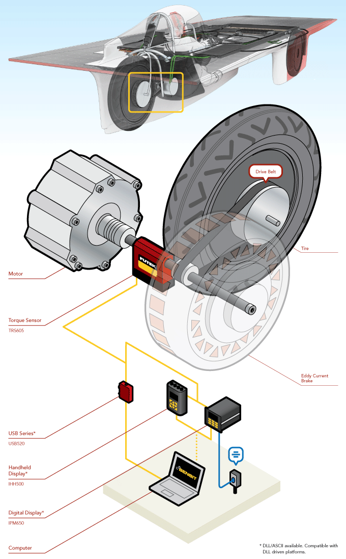
Stanford Solar Car Dyno
How it Works
- The Stanford Solar Car Project team wanted to add a clever twist to their dynamometer (dyno): implement one of Xenith’s regenerative brakes as its energy absorber.
- This setup would allow them to simultaneously study the efficiency of their regenerative braking system while testing their motor.
- To gain perspective on if this approach could be realized, the SSCP Team called on the experts at FUTEK.
- Consulting led to a clear direction that their dyno would need a TRS605 Rotary Torque Sensor at the center of its measurement system.
- The TRS Series sensor integrates a rotary encoder with a freely spinning torque transducer.
- The TRS605 could then be situated directly between the motor’s crankshaft and the regenerative brake allowing the both torque and displacement measurements to be simultaneously captured by a single sensor.
- The USB520 is the ideal data exchange solution for systems that require translation of rotary torque encoder readings, such as angle and speed. Its compact and robust design also makes the USB520 fitting for this type of application.
|
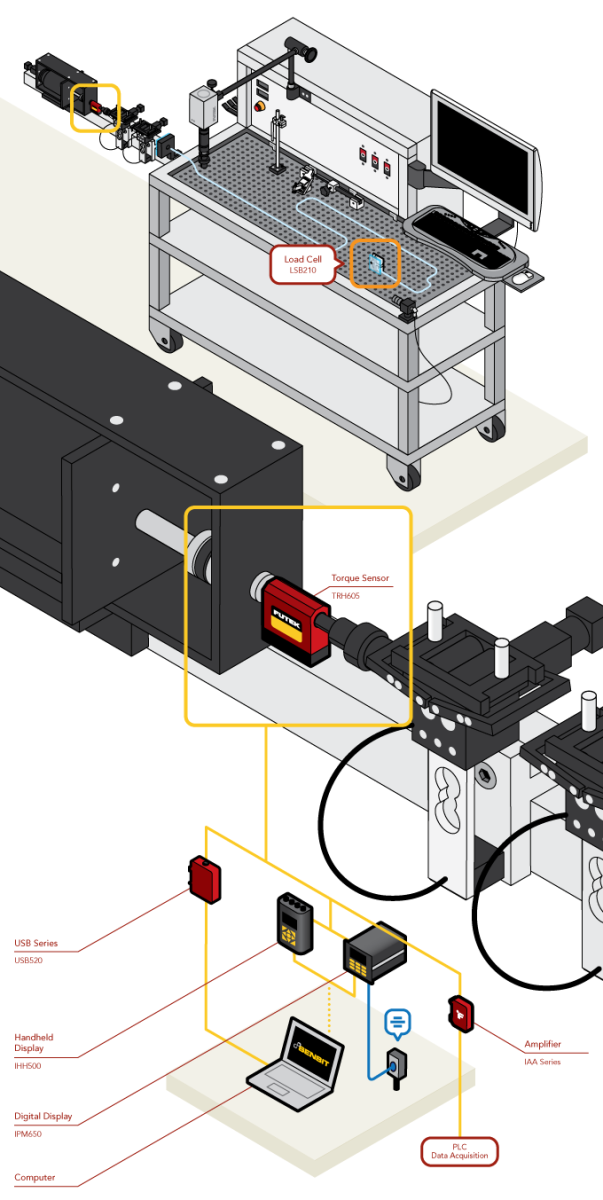
Catheter Torque Test
How it Works
- The purpose of an interventional device test is to reduce risk to the patient during medical procedures. Medical researchers conduct test with these systems to learn more about their performance features such as torqueability.
- Torqueability or torque force refers to the measure of rotational feedback at the distal end of a device while imparting a rotation at the proximal end. Precise measurement modules are needed to accurately record findings pertaining to rotational force.
- The TRH605 is fixed on the test system to quantify the rotary force exerted to advance the catheter through a tortuous anatomy (Test Tube).
- These force measures can be streamed to a computer utilizing FUTEK's USB Solutions. FUTEK’s USB modules are configured by the ASCII stream along with the DLL which allows users to integrate custom software if needed.
- Once streamed to a computer, that data can then be monitored by FUTEK's SENSIT™ Test and Measurement Software.
|
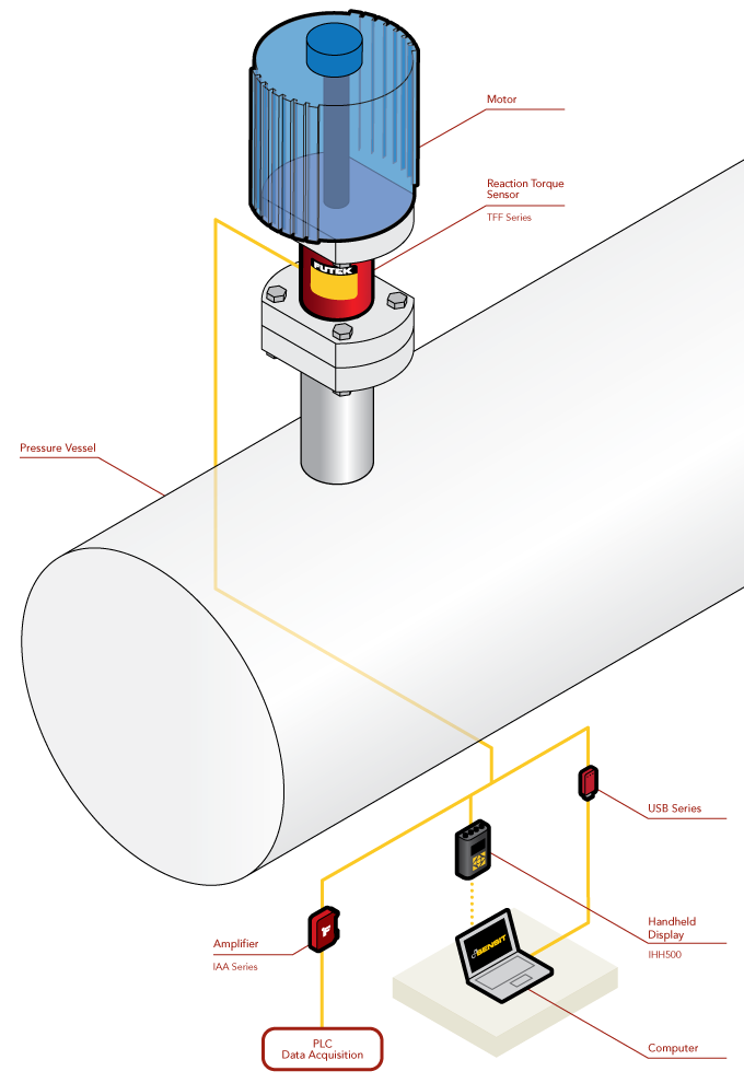
Valve Torque Testing
How it Works
- In this application, a Reaction Torque Sensor is mounted between the electric valve actuator and valve housing.
- The valve stem passes freely through and does not make contact with the Reaction Torque Sensor.
- The TFF Series Reaction Torque Sensor measures the torsion/torque moments required by the valve actuator to operate the valve.
- The TFF Series measurements are then outputted to a digital display (IHH500), streamed to a PC using FUTEK’s USB solutions, or amplified with IAA series for using with PLCs and data acquisition devices.
- In addition, data can be viewed in real time and logged by operators using FUTEK’s SENSIT™ Test and Measurement Software.
|
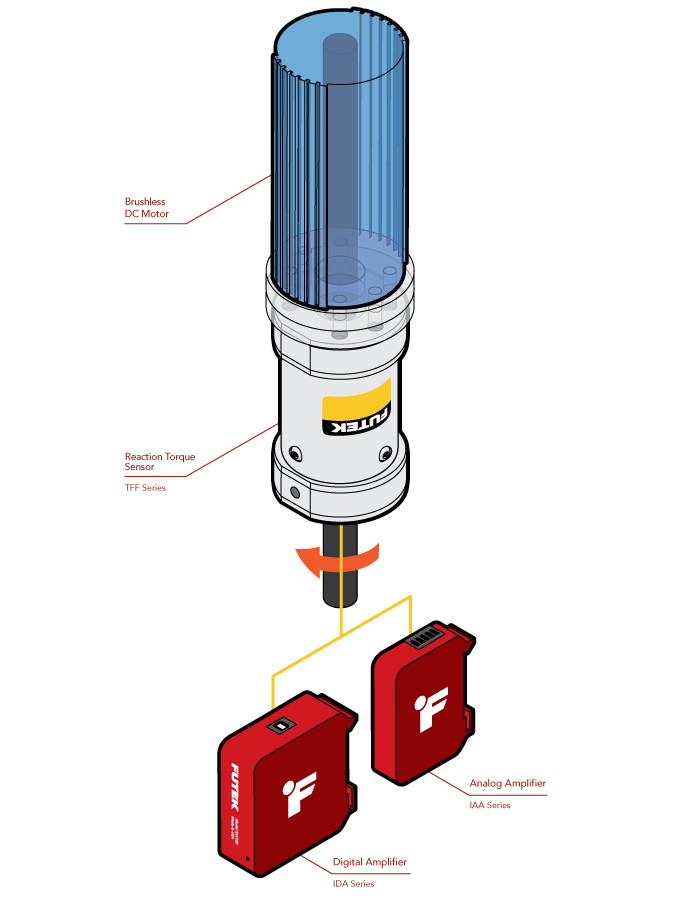
OEM Torque Motor Test Stand
How it Works
- In this application, a reaction torque sensor is mounted to the electric motor with the motor shaft passing freely through the torque sensor.
- For optimal performance of the reaction torque sensor, the free end of the sensor, as pictured, must be fixed.
- The TFF Series measures the reaction torque/torsion moments created by the miniature electric motor during operation.
- These measurements are then amplified with IAA Series or IDA100 for use with PLCs and data acquisition devices or streamed to the PC with IDA100 over USB.
- In addition, with the IDA100, data can be viewed in real time and logged by operators using FUTEK’s SENSIT™ Test and Measurement Software.
|
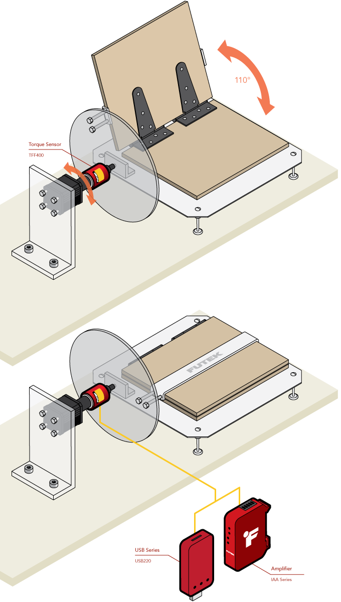
Hinge Fatigue Testing
How it Works
- The TFF400 torque sensor is mounted in line with the motor driving the automated cycling system.
- Although the TFF400 is a reaction torque sensor, if the overall rotation is less than 360 degrees, you avoid the risk of the cable winding around the sensor.
- The TFF400 is then mounted to the hub of a wheel. The rotation of the wheel will allow the hinge that is to be tested to open and close.
- The TFF400 will then record the amount of torque needed to open and close the hinge.
- If the motor is set in brake mode, the torque sensor will be able to measure the torque spring resistance and torsional stiffness.
- A TFF400 paired with a USB220 can output the results of testing to a PC for data capture and analysis.
- Additionally, a TRS605 paired with USB520 will allow for the logging of rotary angle data, enabling a study of torque versus hinge angle.
|
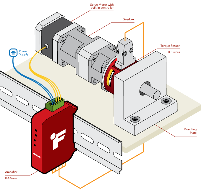
Servo Motor Torque Control
How it Works
- FUTEK's TFF500 Reaction Torque Sensor is mounted between a CGI Prime 017PLX Planetary Angle Gearhead and the gearhead’s mounting location.
- As the servo motor runs, the torque produced and transmitted through the NEMA 17 gearhead is measured by the TFF500.
- The IAA analog amplifier amplifies the TFF500 signal for input into a PLC for closed loop control of torque.
|
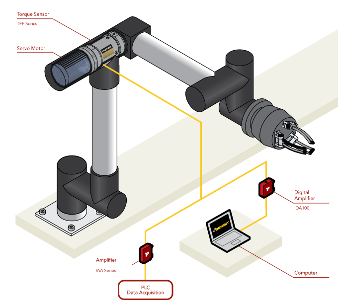
Torque Sensors for Robot Joint Control
How it Works
- A TFF Series Reaction Torque Sensor is mounted between the robot arm servo motor and it's mounting points.
- The torque sensor measures the torque outputted during arm movement which is then amplified by the IAA Series or IDA100 amplifier.
- The amplified signal is then sent to the PLC or robotic arm controller, providing precision feedback and closing the control loop.
- Additionally, with the IDA100, amplified output from the sensor can be monitored and analog amplifier settings can be adjusted digitally with FUTEK's SENSIT™ Software.
|
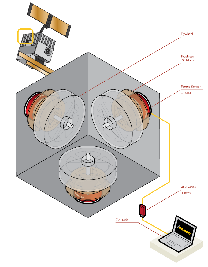
Satellite Reaction Wheel Torque
How it Works
- As an electric motor spins a flywheel, the torque generated is used to provide attitude stabilization about the axis the motor is mounted on.
- The QTA141 Micro Reaction Torque Sensor is mounted between a brushless DC motor and the wall of the satellite.
- As the electric motor spins the flywheel up to the commanded rotational velocity, the resulting torque is reported by the QTA141 Torque Sensor.
- The torque generated is used to provide attitude stabilization about the axis the motor is mounted on.
- The measured torque is then displayed and recorded with the USB220 via FUTEK’s SENSIT™ software.
|
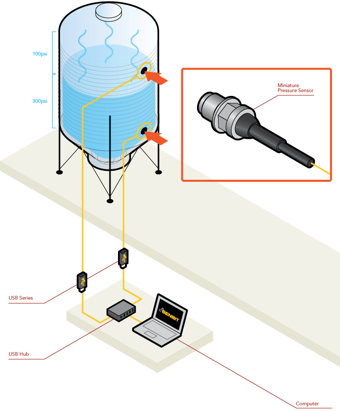
Differential Pressure Measurement
How it Works
- In this application, engineers and/or operators have installed two miniature differential pressure sensors to monitor the ratio of liquid to gas within the tank.
- As illustrated, the pressure of the fluid within the tank measures at 300 PSI, while the emitted gases measures at 100 PSI.
- These measurements are streamed through FUTEK's USB Solutions to a PC utilizing FUTEK's SENSIT™ Test and Measurement Software. This software will calculate the differential pressure within the tank.
- In this specific case, SENSIT™ will calculate the differential pressure as 200 PSI.
|