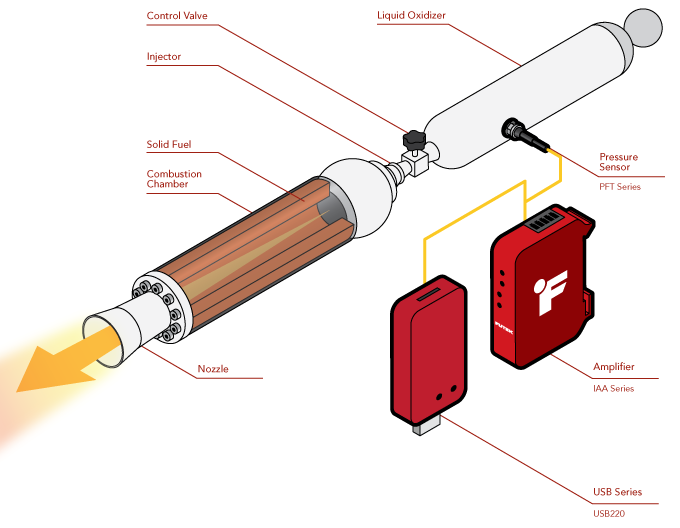
Hybrid Rocket Propulsion Pressure Monitoring
How it Works
- A PFT Series pressure sensor is threaded in and mounted flush with the inner walls of the oxidizer tank.
- During operation, tank pressure is measured by the pressure sensor.
- Output can also be streamed and logged via the USB530 to a PC running SENSIT or connected to a PLC or DAQ with the IAA300.
|
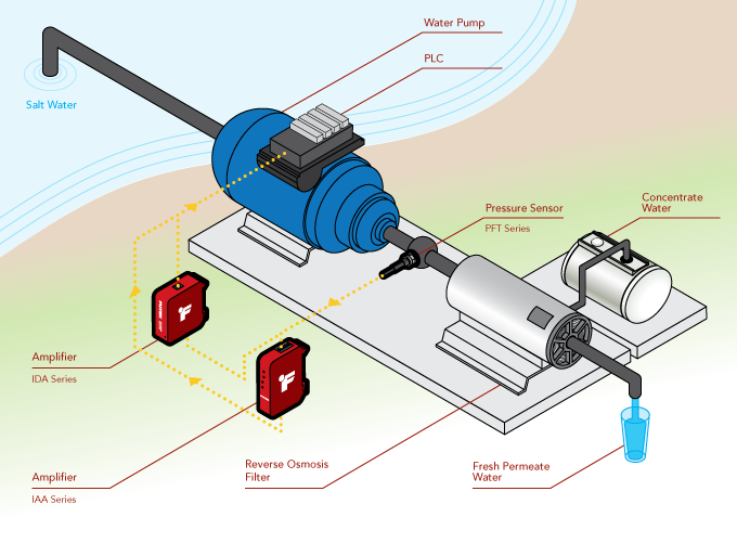
Desalination System Monitoring
How it Works
- A PFT510 miniature pressure sensor is inserted between the water pump output and reverse osmosis filter input.
- The output signal from the pressure sensor is amplified with the IAA series or IDA100 amplifier and fed into a PLC.
- The PLC regulates the motor output in response to changing pressures maintaining a constant output pressure.
- By maintaining a consistent pressure, filter life is increased and system efficiency is maximized.
- Additionally, with the IDA100, amplifier output can be monitored and adjusted accordingly over USB connection with FUTEK's SENSIT™ software.
|
Ghost Containment Monitoring
How it Works
- Once the Ghostbusters have locked a ghost (a Class V Full-Roaming Vapor or weaker) into place with a one or more confinement beams, they need to capture it. This is where their patented Ghost Trap comes into play.
- Once inside the trap, the ghost is broken down and held in place with a laser containment grid.
- However, no ghost wants to stay trapped for eternity, so they attempt to break free from their prison by reforming themselves.
- The reforming process exerts pressure on the trap walls which is measured by the PFT510 Pressure Sensor.
- The pressure measurement is then fed into the trap’s controller enabling it to adjust its containment field in real time.
|
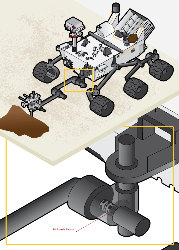
MSL Mars Rover Cryogenic Multi-Axis
How it Works
- Many applications require customized solutions. Thus, FUTEK knows that when NASA approaches us, a standard off-the-shelf product won't fully fit their bill of requirements. But being that we are in the business of providing solutions, if there's a will there's a way for FUTEK to design and develop the necessary sensor needed for the job. And that's exactly what we did.
- For the MSL Mars Rover Curiosity mission, FUTEK was commissioned by NASA JPL to develop a space/flight qualified cryogenic three component sensor. With capabilities of measuring torque and force, this sensor operates within the rover's robotic arm. As the arm maneuvers, the multi-axial sensor provides feedback to the operating device identifying the levels of torsion and force applied. The necessity of this multi-axial sensor is to alert the rover if over-exertion on the arm occurs.
|
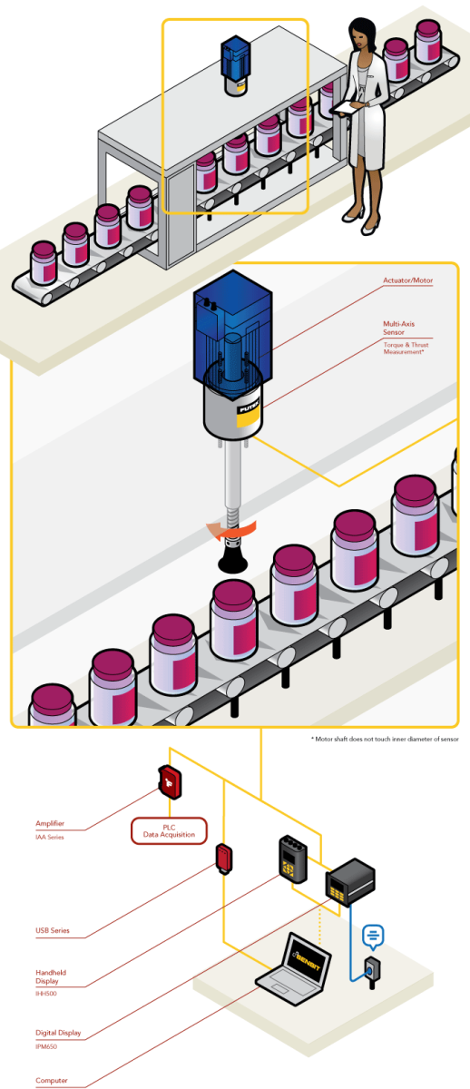
Automated Capping Press
How it Works
- Operators have installed a biaxial sensor into their production line to monitor the actuator/motor powering the capping press.
- Installed directly underneath the capping press' actuator, this biaxial sensor measures the torque and thrust exerted as each cap is sealed onto its respective container.
- These torque and thrust measurements can be amplified through FUTEK's IAA Series Amplifier to a PLC, shown on a digital display (IPM650 or IHH500) or streamed directly to a PC using FUTEK's USB Solutions.
- If the instrument is paired with FUTEK's SENSIT™ Test and Measurement Software operators can log, graph and capture all the data on the PC.
|
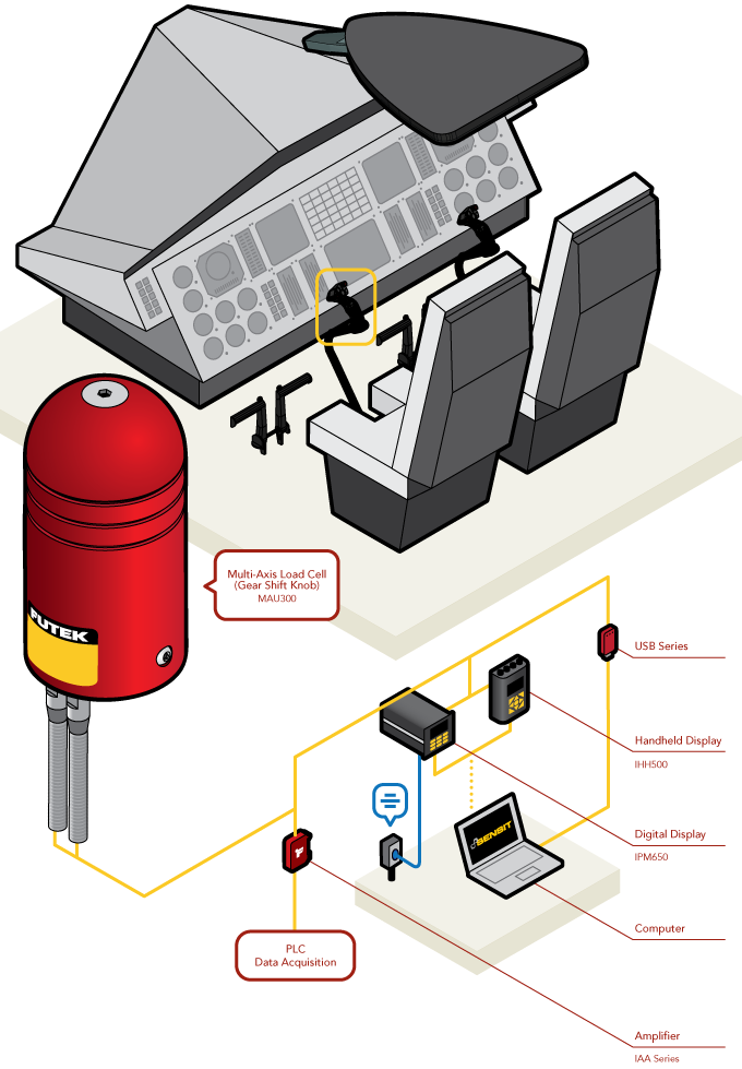
Helicopter Cyclic Control Sensors
How it Works
- Helicopter cyclic controls (joysticks) are responsible for lateral and longitudinal movements of the aircraft.
- To ensure that these mechanism are operating properly, quality assurance engineers can install FUTEK's MAU300 Multi-Axis Gear Shift Load Cell into the shaft of each joystick.
- The MAU300 performs measurements in both the Fx and Fy directions.
- These force measurements can be read upon a digital display, such as FUTEK's IPM650 Panel Mount Display or IHH500 Intelligent Digital Hand Held Display, or streamed to a PC utilizing FUTEK's USB Solutions.
- Once streamed to a PC, that data can then be monitored by FUTEK's SENSIT™ Test and Measurement Software. SENSIT™ can monitor up to 16 channels of measurement readings, as well as live graph and data log.
|
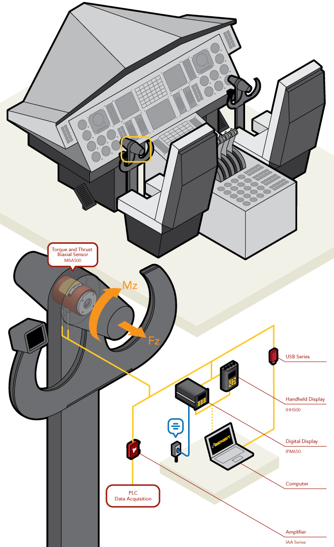
Aircraft Control Column Torque Measurement
How it Works
- Pilots rely heavily on the control column (yoke) to guide the pitch and roll of a plane. By rotating the yoke, a pilot maneuvers on the roll axis. By propelling the yoke forward and backward, that pilot can adjust the elevation and pitch axis.
- To ensure that the control column is operating properly, quality assurance engineers can install FUTEK's MBA500 Torque and Thrust Biaxial Sensor into the yoke.
- The MBA500 performs measurements in both the Mz (the roll) and Fz (the pitch) directions.
- These torque and thrust measurements can be read upon a digital display, such as FUTEK's IPM650 Panel Mount Display or IHH500 Hand Held Display, or streamed to a PC utilizing FUTEK's USB Solutions.
- Once streamed to a PC, that data can then be monitored by FUTEK's SENSIT™ Test and Measurement Software.
|
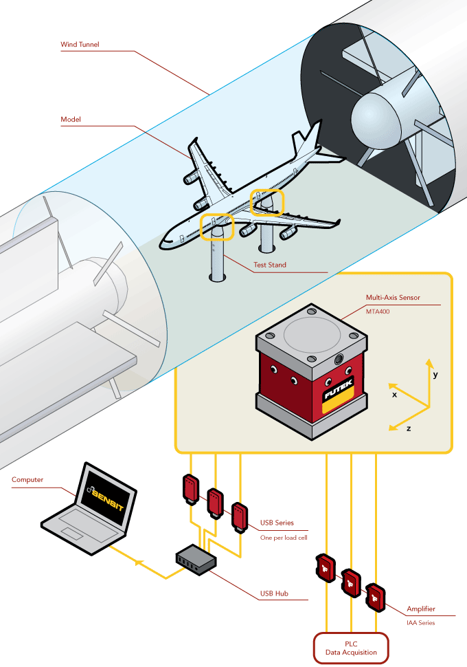
Wind Tunnel Testing
How it Works
- Researchers use wind tunnels to learn more about the relationship between airflow and an object. Precise measurement modules are needed to accurately record findings.
- The MTA400 is fixed on a test stand to quantify the force placed on a model. The model is then fastened onto the Tri-Axial Load Cell which will record precise pressure measurement in response to the conditions of the wind tunnel.
- These force measures can be streamed to a PC utilizing FUTEK's USB Solutions.
- Once streamed to a PC, that data can then be monitored by FUTEK's SENSIT™ Test and Measurement Software. SENSIT can monitor up to 16 channels of measurement readings, as well as live graph and data log.
|
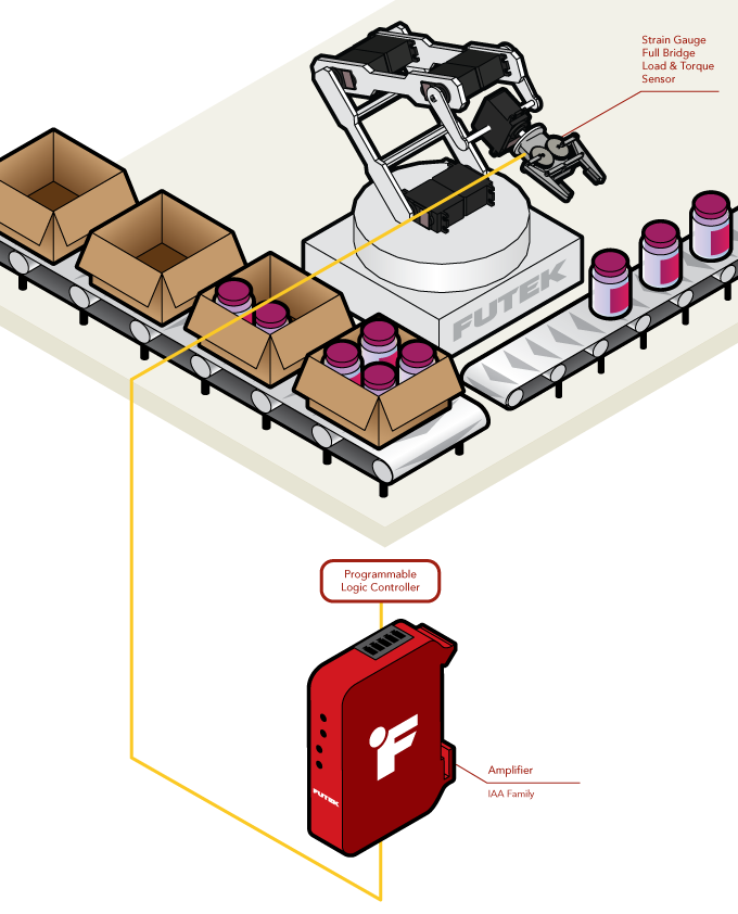
Industrial Automated Robotic Arm
How it Works
- In order to automate an industrial robotic arm, control engineers will program a PLC to specify response triggers.
- In the above diagram, a full-bridge strain-gauge-based load and torque sensor resides within the claw of the robotic arm measuring torque and load of an object.
- The IAA Series amplifies a mV/V signal coming from the strain-gauge-based sensor.
- The output of the IAA amplifier will produce an accurate and low noise signal to the PLC to complete the feedback loop. (Because this application is utilizing a multiple channel sensor, the operations engineer will require one IAA amplifier per channel output.)
|
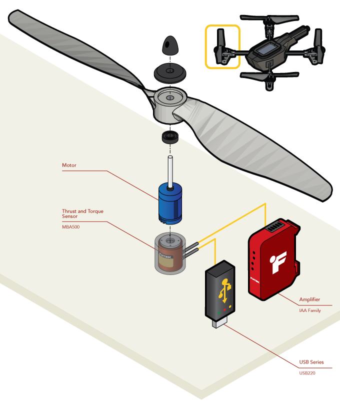
Quadcopter Propeller Torque and Thrust Testing
How it Works
- In order to characterize the thrust and torque generated by each motor and propeller, a MBA500 is fixed to the motor's end.
- When the motor is powered on and rotating, the thrust of the propellers will be measured by the MBA500’s Fz channel, and the back-torque of the motor is measured by the Mz channel, all while maintaining low crosstalk.
- This multi-axial sensor, when used with a USB220, allows for a portable setup where a hobbyist/test engineer can use a laptop to analyze the live data of a test both in an outdoor setting or in a more controlled, indoor environment.
|