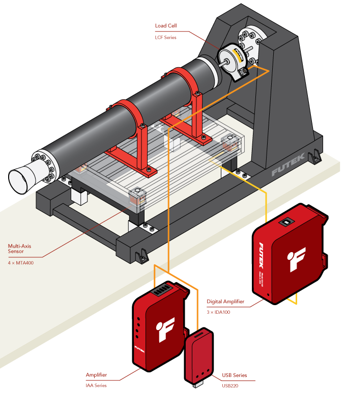
Rocket Engine Thrust Stand
How it Works
- In this application, the rocket engine is threaded into the LCF series universal load cell.
- The engine mount prevents any side loading on the cell, ensuring the load cell is only receiving axial loads.
- The load cell assembly is mounted to a fixed test stand securing the engine.
- In line with the base supports, MTA400/MTA600 multi-axis load cells are installed.
- As the engine is operating, thrust is measured with the LCF series load cells.
- Mass flow and Drag(aka “kick”) are captured with MTA400/MTA600 load cells.
- Thrust data can be live streamed and logged for monitoring and later review and comparison against simulated models with USB220 and SENSIT.
- Mass flow data from all 4 multi-axis load cells are captured, streamed and logged with USB220 and SENSIT.
- Each axis of the MTA400/MTA600 is captured with a separate USB220.
- Load cell output can also be amplified via the IAA series for capture by pre-existing DAQs.
|
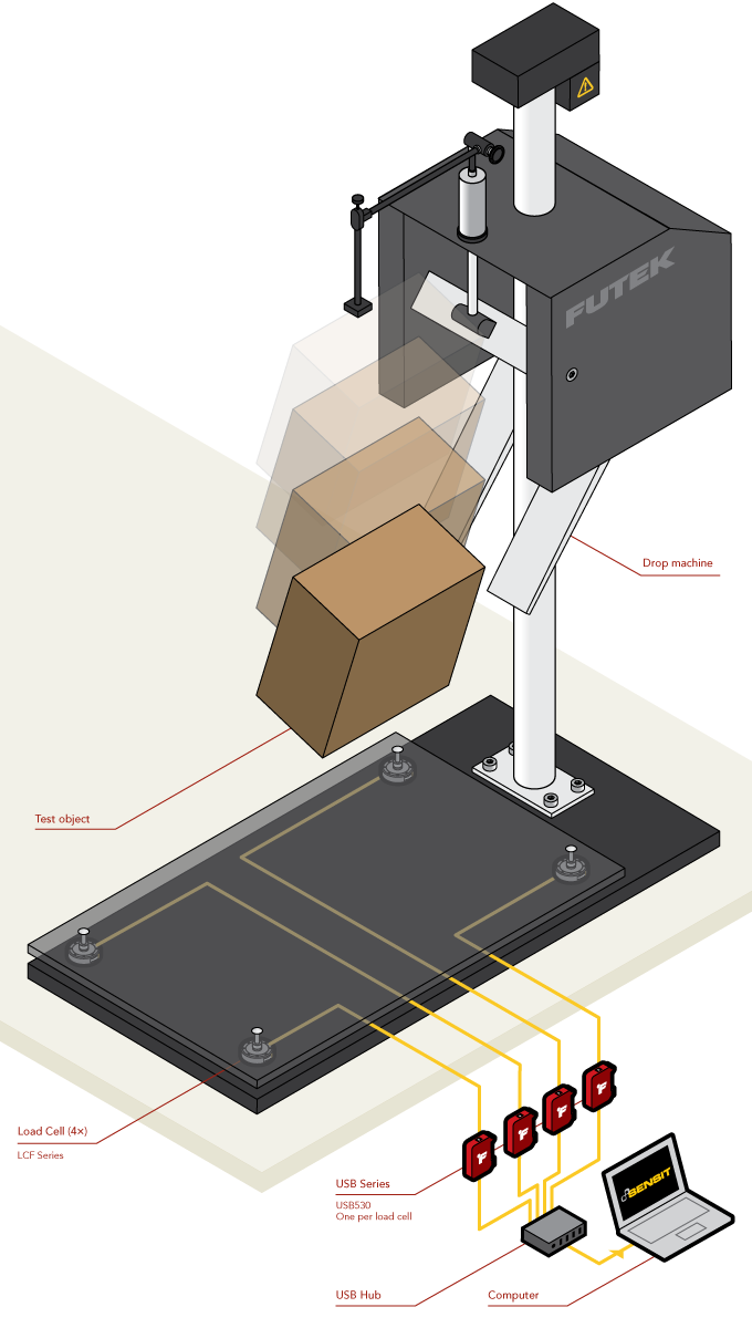
Package Drop Test Machine
How it Works
- Four LCF series pancake load cells are mount on the four corners of the drop test machine base. The test platform is then bolted over the four load cells.
- When a package is dropped, the load cells in each corner measure and send load data to the USB530 data acquisition unit.
- The data collected is displayed, logged, and graphed via our SENSIT™ software on a PC.
- By changing out the test platform, different drop scenarios can be simulated and recorded for study and compliance with testing standards such as ASTM D5276 and ISTA 1a, 2a, and 3a.
|
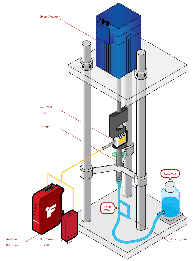
Medical Valve Sensors: TAVR Fatigue Testing
How it Works
- LSB series load cells are threaded in-line with a linear actuator and syringe piston which measures the force the linear actuator applies to the syringe piston for test validation.
- As the linear actuator pushes down on the load cell/piston the flow of fluid pushes the TAVR valve open.
- A check valve keeps the fluid moving through the TAVR valve and a reservoir prevents the system from pushing air which would invalidate the test.
- The linear actuator then retracts, pulling the piston up, thereby forcing the TAVR closed and refilling through the now open check valve.
- This cycling allows for testing of the durability of the replacement valve in a simulated aortic environment for compliance with ISO 5840 series standards.
- The USB220 displays and logs the data to a PC via our SENSIT™ software. This data can be used to validate the accuracy and precision of the pressure generated by the syringe piston.
- The IAA series amplifier, amplifies the signal for use in DAQs that cannot accept a mV/V signal.
|
Prosthetic Hip Fatigue Testing
How it Works
- The femoral stem of a prosthetic hip joint is fastened into a test fixture. The femoral head is then attached to special acetabular cup.
- A LCF300 universal pancake load cell is then mounted between the acetabular cup and a linear actuator for applied force measurement during testing.
- During testing, the signal from the LCF300 load cell is sent to the IDA100 Digitally Configurable Amplifier. The IDA100 generates an amplified analog signal that can be fed back into the test setup PLC for closed-loop control
- The digital signal from the IDA100 is streamed over USB to FUTEK’s SENSIT™ software for display/logging/and graphing for compliance with ISO 7206-4, 6 and PI-58 (ISO 7206-8), and ASTM F 2580.
- The IDA100 is capable of digital configuration, allowing sensor calibration and amplifier gain and span settings all controllable from a PC equipped with SENSIT.
- The LCF300 is one of FUTEK’s sensors least sensitive to extraneous loads. In scenarios with extraneous loading, the LCF300 provides accurate test data when perfect in-line measurement is not an option.
- Optionally, the MTA500 multi-axis load cell can be used to measure forces along the Z axis and moments about the X and Y axes.
|
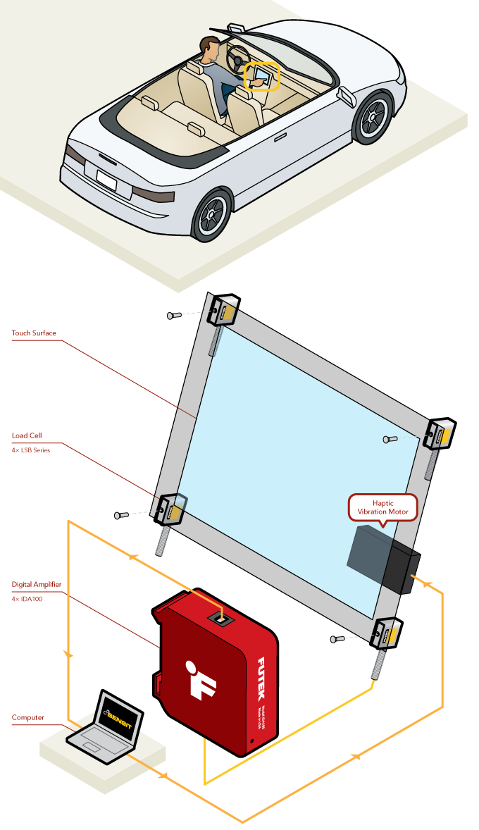
Automotive Touchscreen Haptic Feedback
How it Works
- An LSB200 Jr. Miniature S-Beam Load Cell is placed behind each of the touch screen bezel mount points. A bolt passes through each load cell holding both the screen and load cell in place.
- As the user taps the screen, the load cells measure the tap force.
- This force is then amplified via the IDA100 which is running off the cars 12V accessory power line.
- The amplified signal is sent to the entertainment systems computer which drives a vibrator motor proportionally in response to the contact force.
|
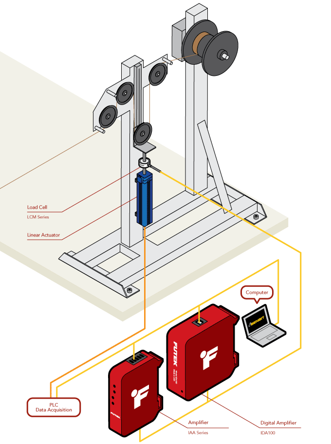
Precision Wire Tensioner
How it Works
- An LCM Series Miniature In Line Load Cell is mounted in-line between the wire tensioner and a linear actuator to measure wire tension.
- Adjusting the linear actuator piston causes changes in wire tension which generates a signal in the LCM series load cell.
- The signal from the LCM series load cell is then sent to the IAA series Analog Amplifier or IDA100 Digitally Configurable Amplifier.
- The amplified signal is then fed into a PLC/Motion Controller which drives the liner actuator, closing the control loop, and allowing the system to actively adapt to changing wire conditions.
- With the IDA100, amplifier output can be simultaneously monitored and adjusted on a Windows PC with FUTEK’s SENSIT™ software while providing high speed, amplified, analog output.
|
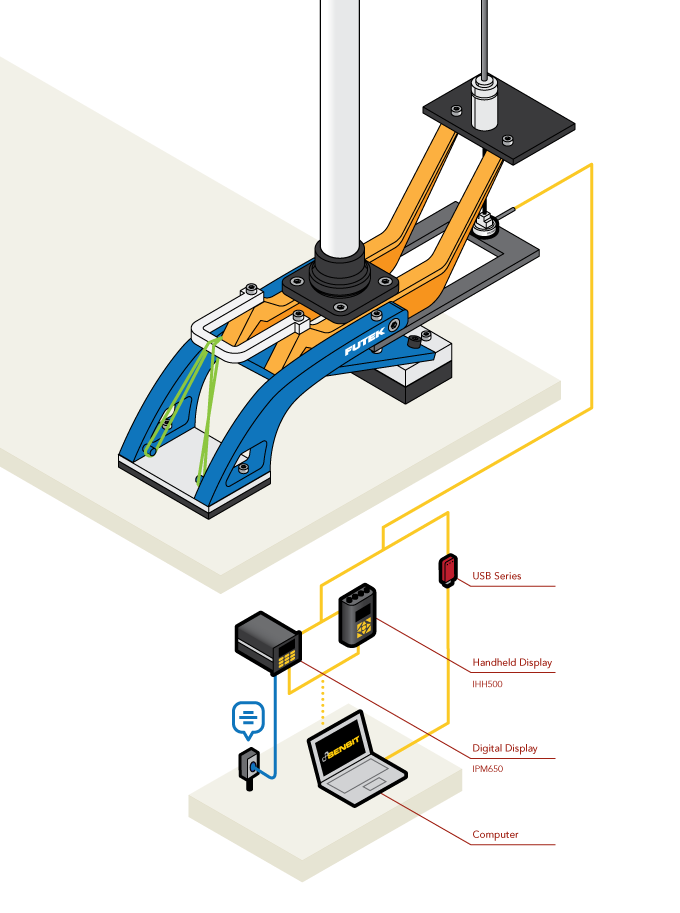
Prosthetic Foot Emulator
How it Works
- One end of the LCM200 is attached to the control wire attached to the servo driven cable actuator.
- The opposite end of the LCM200 is mounted into the heel of the prosthesis.
- As the individual walks, the cable pulls on the heel of the prosthesis mimicking the torque generated in walking by an Achilles Tendon.
- The force used to actuate the heel is measured by the LCM200 and displayed with the IPM650 Digital Panel Meter, IHH500 Handheld Display, or on a PC using the USB220 High Resolution Output Module and our SENSIT™ software.
- The instruments are then connected to a PC over USB 2.0 which drives the servo motor, closing the control loop, and allowing the system to actively adapt to an individual’s gait.
- With the IDA100, amplifier output can be simultaneously monitored and adjusted on a Windows PC with our SENSIT™ software while providing high speed, amplified, analog output for PLCs and Motion Controllers.
|
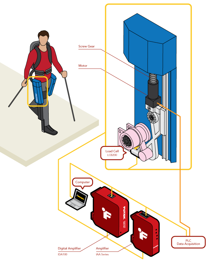
Exoskeleton for Paraplegics
How it Works
- FUTEK sponsored their exoskeleton by providing our LCB200 load cells, which were installed in specialized fixtures IHMC designed, enabling the system to receive accurate force feedback from the motors and closing the control loop, all while allowing the sensor to safely rotate.
- A LCB200 is installed in a specialized fixture attached to the motor, allowing it rotate like a human joint, minimize extraneous loads, and provide accurate load data.
- As the motor operates, it applies force to the joint, rotating it. This force is measured by the LCB200.
- The mV/V signal from the LCB200 is sent to the IAA series analog amplifiers or IDA100 digitally configurable amplifier.
- The amplified signal is sent to the exoskeleton’s control system, using the amplified load cell output to close the loop and drive the exoskeleton’s motors.
- With the IDA100, amplifier output can be simultaneously monitored and adjusted on a Windows PC with FUTEK’s SENSIT™ software while providing high speed, amplified, analog output.
|
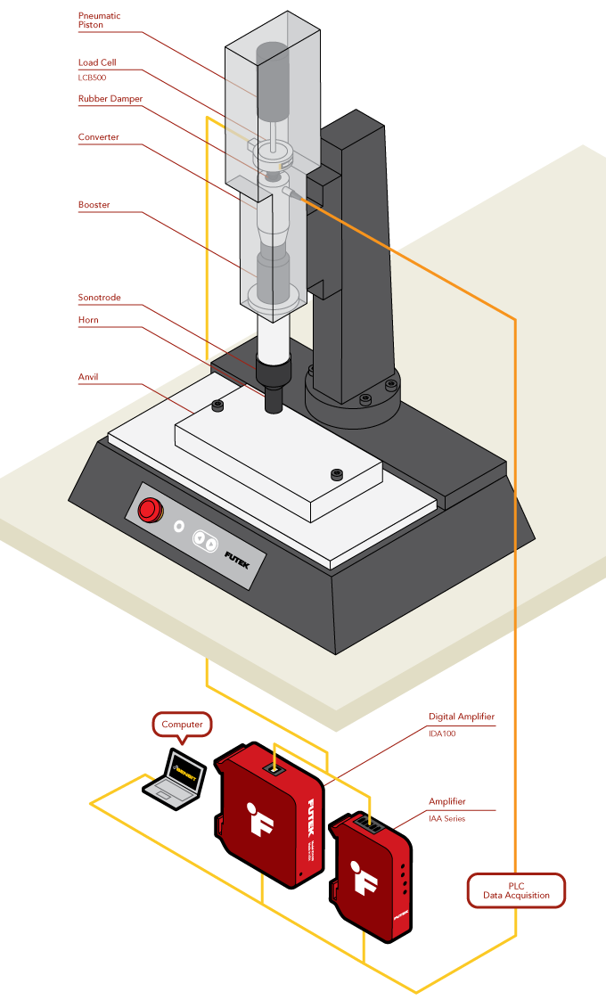
Ultrasonic Welding Clamp Force
How it Works
- A LCB/LCF Series Load Cell is mounted between the converter and the actuator that moves the assembly/stack.
- A dampener is placed between the converter and LCB/LCF load cell to minimize the effects of high speed vibrations on the sensor.
- As the assembly clamps the parts together, the LCB/LCF load cell measures the welding and hold time clamping forces.
- The IAA Series and IDA100 amplify and transmit the load cell signal to the welder's PLC enabling closed loop clamping force control.
- Additionally, the IDA100 enables logging and monitoring of the load cell output via a PC with SENSIT™ Software.
- The data generated via our SENSIT™ software can then be used for IoT and production traceability operations.
|
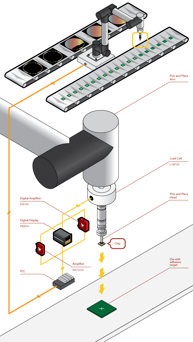
Die-Attach Force Measurement
How it Works
- A LCM100 Miniature In Line Load Cell is between the pick and place head and armature.
- As the armature presses the chip down onto the die during the attach process, the LCM100 measures the force applied.
- The force applied is then displayed by IHH500 Intelligent Digital Hand Held Display or IPM650 Panel Mount Display.
- Utilizing the IAA300 analog amplifier or the analog outputs from the IDA100 or IPM650, an amplified output can be sent to a PLC for automated die attach processes.
- The ultra-low noise output from the IAA300 makes it ideal for high precision motion control.
|