 |
|
|
|
Measuring and inspection systems for rubber and tires
The rubber processing industry, as well as the tire production process is supported by Micro-Epsilon with a range of systems for inspection, monitoring and control of miscellaneous processes.
|
|
|
|
|
 |
|
|
|
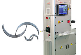
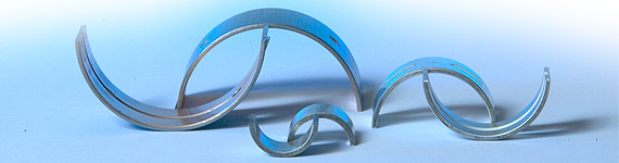
Bearing shells thickness measurement
The quality assurance of bearing shells is determined by the extremely precise specification of several characteristics. Dimensional measured values such as thickness and diameter are also included with the surface quality in the quality inspection. Micro-Epsilon provides several systems using different technologies for the determination of the respective quality criteria.
Advantages:
-
Short cycle times for in-line process
-
No mechanical damages
-
Wear free measurement
-
Easy adaption to diffferent bearing shell diameters
Material parameter:
-
Diameter 30mm to 85 mm
-
Width 15mm to 60mm
-
Thickness 1.5mm to 5mm
|
|
|
|
BS 8251.I
The system for bearing shells thickness measurement is an in-line system for non-contact wall thickness and profile measurement of bearing shells for automotive use. The air cushioning and the completely automatic transport make it possible to inspect up to 60 shells per minute.
|
|
|
|
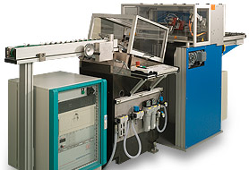
BWS 8202
The system for bearing shells thickness measurement is an in-line system for non-contact wall thickness and profile measurement of bearing shells for automotive use. The air cushioning and the completely automatic transport make it possible to inspect up to 60 shells per minute.
|
|
|
|
back to product group "Measuring and inspection systems for metal" |
|
|
|
|
 |
|
|
|
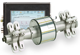
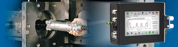
Non-contact inspection of extruder bores
Applying the IDS 8100.C the diameter of case bores of extruders can be detected precisely. The wear of the machine which has been generated due to abrasive raw material, temperature and pressure can be controlled without contact.
Advantages:
-
Significant reduction of the service time
-
Allows the exchange of defective segments
-
Suitable for all metals without further calibration
-
Local evaluation with touchscreen controller
Material parameter:
-
Housing diameters from 40 mm to 180 mm
-
Diameter variantions 8 or 16 mm
-
Suitable for all metals
|
|
|
|
IDS 8100.C
The IDS 8100.C works with integrated capacitive displacement sensors. The actual bore diameters are detected over the whole process part length. As the axial sensor positions are detected as well using a cable-length measurement system, local deviations in diameter can be reliably and quickly found. In doing so, each sensor position is related to a diameter in the longitudinal axis of the bore hole.
Features:
-
Accuracy 0.04mm
-
Resolution 5mm
-
Max. speed 5 m/s
|
|
|
|
back to product group "Measuring and inspection systems for metal" |
|
|
|
|
 |
|
|
|
Robot motion optimization for automatic welding processes
The WWS 8205 measures the position tolerance of two pieces before welding. The systems calculates the robot motion in order to receive an efficient welding process.
Advantages:
-
Increased production efficiency
-
Simplification of welding processes
-
100% documentation of the production
Material parameter:
-
Suitable for matt and shiny metal surfaces
-
Increased feed rates
-
Consideration of geometrical elements in the semi-finished products
-
Maximum positional tolerance to be measured ±15mm
|
|
|
|
The systems of the WWS 8205 series are available as one channel system, e.g. for testing pipelines, and two channel systems, e.g. for production of T-sections. |
|
|
|
back to product group "Measuring and inspection systems for metal" |
|
|
|
|
|


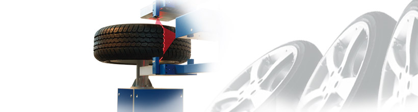

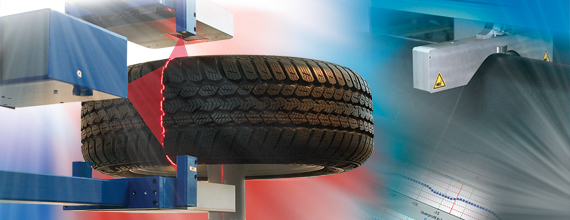
 Suitable for all common TU machines and therefore ideal for retrofit
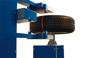
 Tire geometry inline inspection in TU machines
 Non-contact inline profile thickness measurement of roller head installations (thickness 0.3mm to 18mm)