|
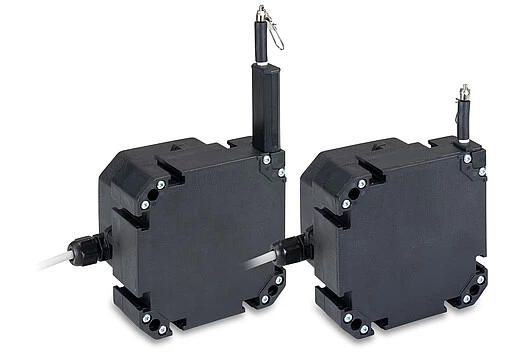
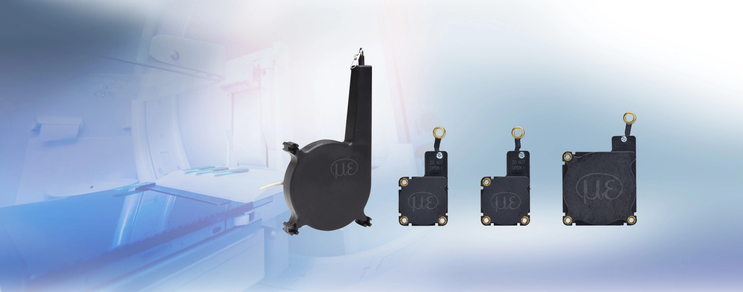
The K100 is specially designed for series use in mobile machines such as telescopic loaders or truck cranes. Its compact and robust housing (IP67/IP69K) made from glass-fiber reinforced plastic and its durable sensor design with separate drum and spring spaces offer increased protection against environmental influences. Specially in outdoor use, these sensors can be optimally adapted to the respective application.
|
|
|


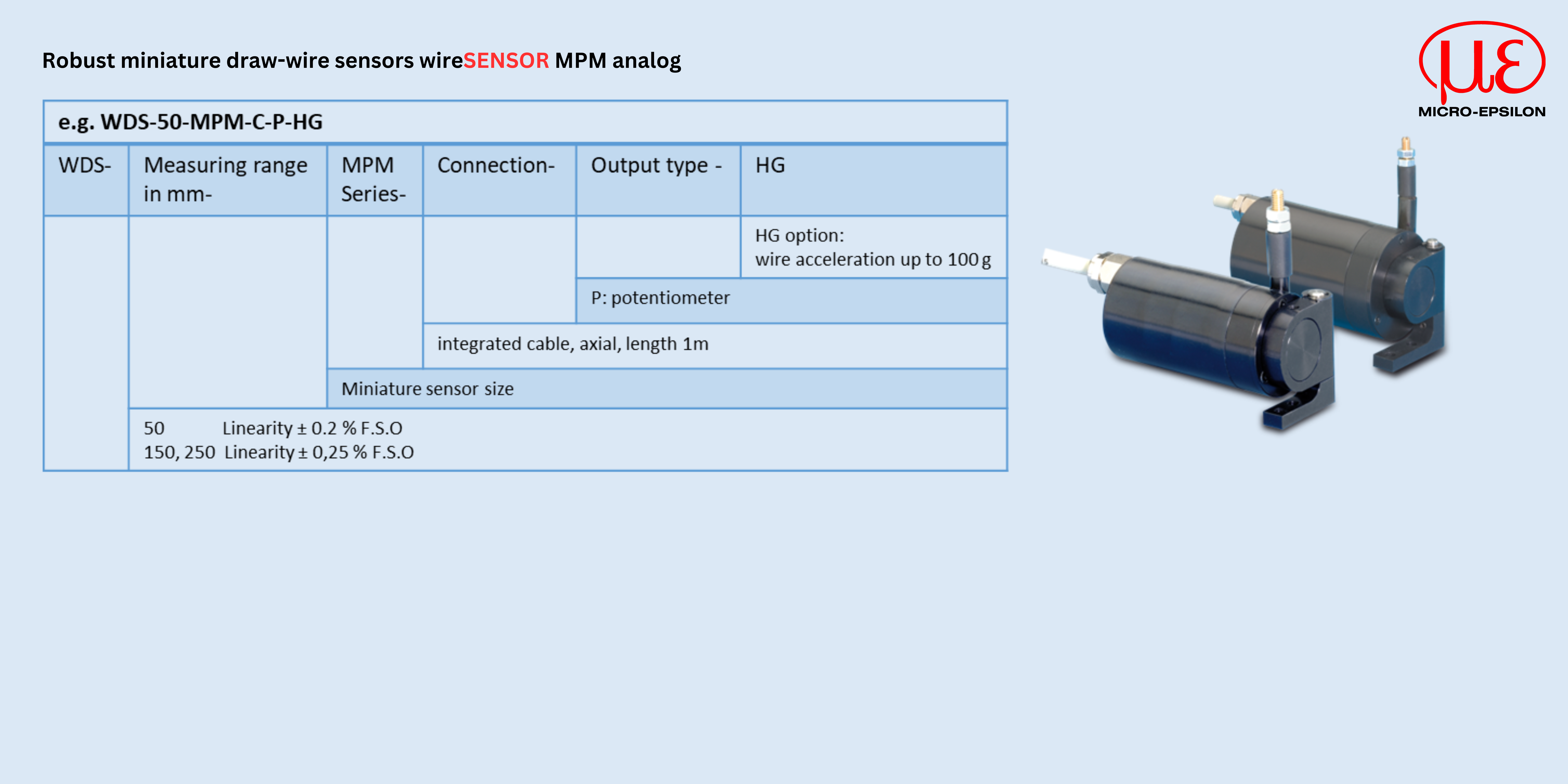
 Measuring ranges (mm): 50 | 150 | 250