 |
|
|
|
|
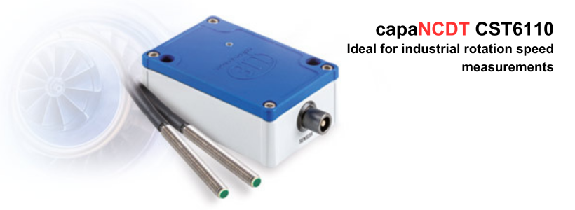
Capacitive rotation speed sensor for industrial measurement tasks
|
|
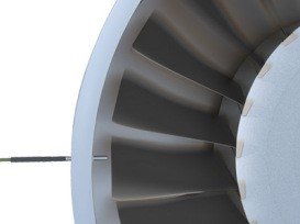
The capaNCDT CST6110 is a capacitive measuring system for non-contact rotation speed measurement of conductive measurement objects such as metals and non-conductive objects such as ceramics or plastics. This non-contact measurement is performed, for example, in drives, on rotor blades or on position marks of shafts. The sensor can be mounted in axial and radial direction to the target in order to detect objects such as blades, teeth, rings or nubs. The measuring range from 1 to 400,000 rpm enables the detection of both the startup from the first rotation and high rotational speeds reliably. The adjustable rotary switch supports the rotation output of objects which have several measuring points per rotation, e.g., rotor blades. Data output is via a voltage output or a digital interface.
|
|
|
How does RPM sensor works?
|
|
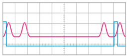
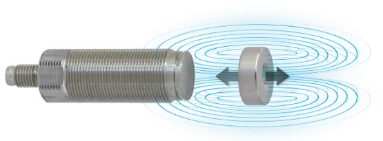
When positioned near a turning rotor, gear, shaft or other regularly moving device, RPM sensors detect the mechanical rotating parts and convert mechanical motion into electric pulses without direct contact. The resultant output signals are then fed to a digital counter, totalizer, tachometer, or other monitoring and control device.
|
|
|
|
|
|
Characteristics
|
-
 Material-independent rotation speed measurement of 1 … 400,000 rpm Material-independent rotation speed measurement of 1 … 400,000 rpm
-
Precise counting from the first detection
-
Adjustable rotary switch (max. 16) for rotation output
-
High interference immunity and reliability
-
Easy integration due to compact sensor size
-
Robust controller with IP67
|
|
|
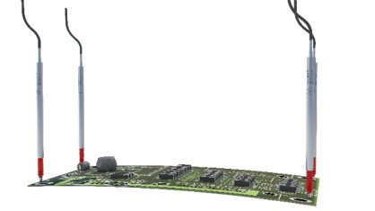
Ideal for industrial counting tasks
|
 |
|
 |
|
 |
|
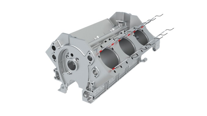
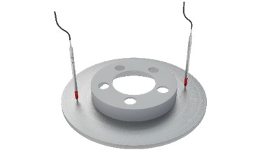
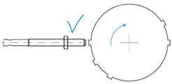
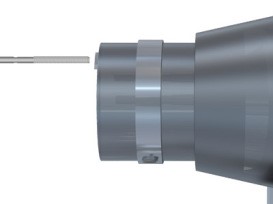
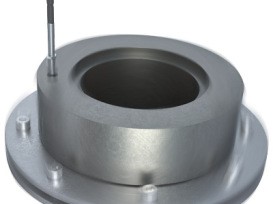
Axial installation: rotation speed monitoring on shafts |
|
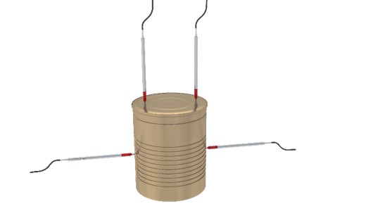
Radial installation: measurement in turbines |
|
Axial installation: rotation speed in drilling rigs |
|
|
|
|
|
 |
|
|
What is the measuring principle of magneto-inductive distance sensors?
|
|
Magneto-inductive distance sensors (Patented Pending).
The mainSENSORis based on an innovative measuring principle developed by Micro-Epsilon in order to combine the advantages of both inductive and magnetic sensors.
|
|
 |
|
|
|
|
A magnet is fixed to the measurement object. The movement of the magnet induces a change in the magnetic flow in the sensor element, which is detected by the sensor coil. A linear relationship between output signal and magnet distance (self-linearization technology) is produced due to counteracting physical effects.
Different magnet with magnet strength are applied thus providing option of difference measuring ranges, up to 55 mm, these sensors are also used in special applications such as rotational speed measurement of, e.g., shafts and gear wheels.
|
|
|
Characteristics
|
-
Ideal alternative to inductive sensors and proximity sensors
-
Linear output signal, high basic sensitivity and temperature stability
-
Selectable measuring ranges up to 55mm with different magnets
-
Long-life sensor due to non-contact measurement
-
Ideal for customer-specific designs and serial applications
|
|
|
Advantages
|
|
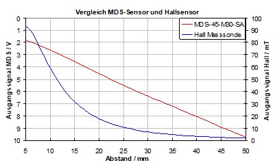
Linear relation between signal and magnet distance (self-linearization) despite large, frontal measuring range
Compared to Hall Effectsensors
Linear output signal
Increased frontal measuring range
Compared to inductive sensors
Significantly larger measuring range
Stable sensitivity at end of measuring range
Compact sensor design (e.g. M12 with MR of 55 mm)
|
|
 |
|
|
|
Flexible sensor concept
|
|
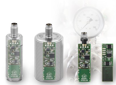
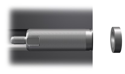
Due to their flexible concept, the sensors are ideal for a wide range of applications, particularly where big quantity and low priceare required. The standard sensors are designed in a stainless steel M12, M18 and M30 or a flat plastic housings suitable for industrial applications. Customer-specific modifications to the plate and sensor housing can be easily carried out for serial applications.
|
|
 |
|
|
|
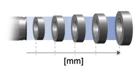
Defining the measuring range using magnets
|
|
With the magneto-inductive measuring principle, the magnets used act as target. To achieve difference measuring range, it is only necessary to change the magnet. Further calibration or sensor settings are superfluous. Therefore, measuring ranges of 20 to 55mm can be achieved using only one sensor.
|
|
 |
|
|
|
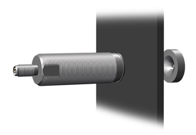
Measurement through objects
|
|
Unlike conventional measuring methods, the magneto-inductive sensors enable measurements through non-ferromagnetic materials, particularly metals such as aluminum or stainless steel. A clear benefit is provided here as the sensor and the magnet can be installed separately in applications with closed systems or housings. It is therefore possible to mount the sensor safely in harsh environments.
|
|
  |
|
|
|
|
|
 |
|
|
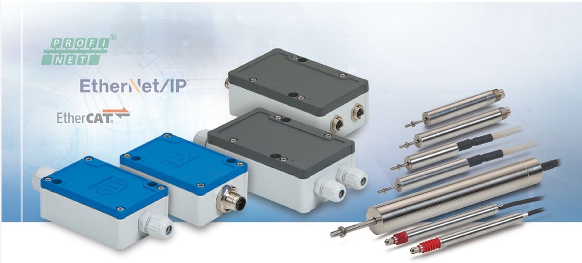
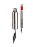
induSENSOR
|
|
Wide variety of models for customer-specific applications
|
|
|
What is the measuring principle of LVDT (Linear Variable Differential Transformer)?
|
|
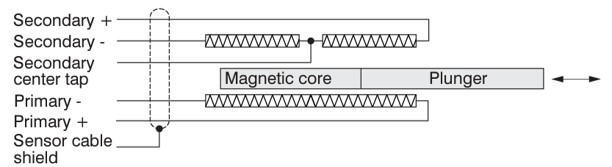
LVDT principle are constructed with a primary and two secondary coils, arranged symmetrically to the primary winding. An electronic oscillator supplies the primary coil with an alternating current of constant frequency (between 1~10 kHz) with a excitation voltage (AC) of a few volts.
As a measurement object (a rod shaped magnetic core) is moved within the differential transformer.
Depending on the core position alternating voltages are induced into the two secondary windings. If the core is located in its "zero position", the coupling of the primary to both secondary coils is equal giving zero output.
|
|
|
|
Movement of the core within the magnetic field of the coil causes a higher voltage in one secondary coil and a lower voltage in the second coil. The difference between the two secondary voltages is proportional to the core displacement. Due to the differential design of the sensor, the LVDT series has very stable output signal for good performance.
|
|
LVDT – Full Bridge
|
|
|
|
|
|
|
|
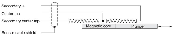
LVDT – Half Bridge
|
|
|
|
|
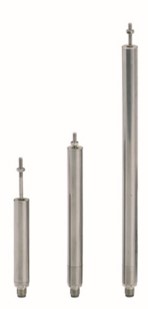
Product series |
Inductive measuring system
DTD Sensor system
|
Gauges with external controller
DTA Gauges
|
Displacement sensors with external controller
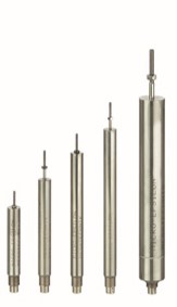
DTA Sensor
|
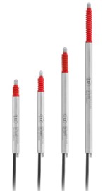
Linear displacement sensors
LDR
|
Robust long-stroke sensors forhydraulics and pneumatics actuator
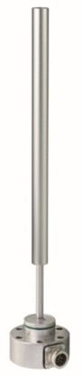
EDS
|
|
Measuring range |
±1 … ±10mm
|
±1 … ±25mm
|
10 … 50mm
|
75 … 630mm
|
|
Linearity |
±0.3%
|
±0.15%
|
±0.5%
|
±0.3%
|
|
Frequency response |
300Hz (-3dB)
|
300Hz (-3dB)
|
300Hz (-3dB)
|
150Hz (-3dB)
|
|
Protection class |
IP67
|
IP67
|
IP67
|
IP67
|
|
Target |
Probe tip
|
Plunger
|
Plunger |
Measuring tube
|
|
Pressure resistance |
|
|
|
50 bar
|
|
|
|
|
|
|
|
|
|
|