 |
| |
|
|
|
|
|
|
| |
|
|
| |
 |
|
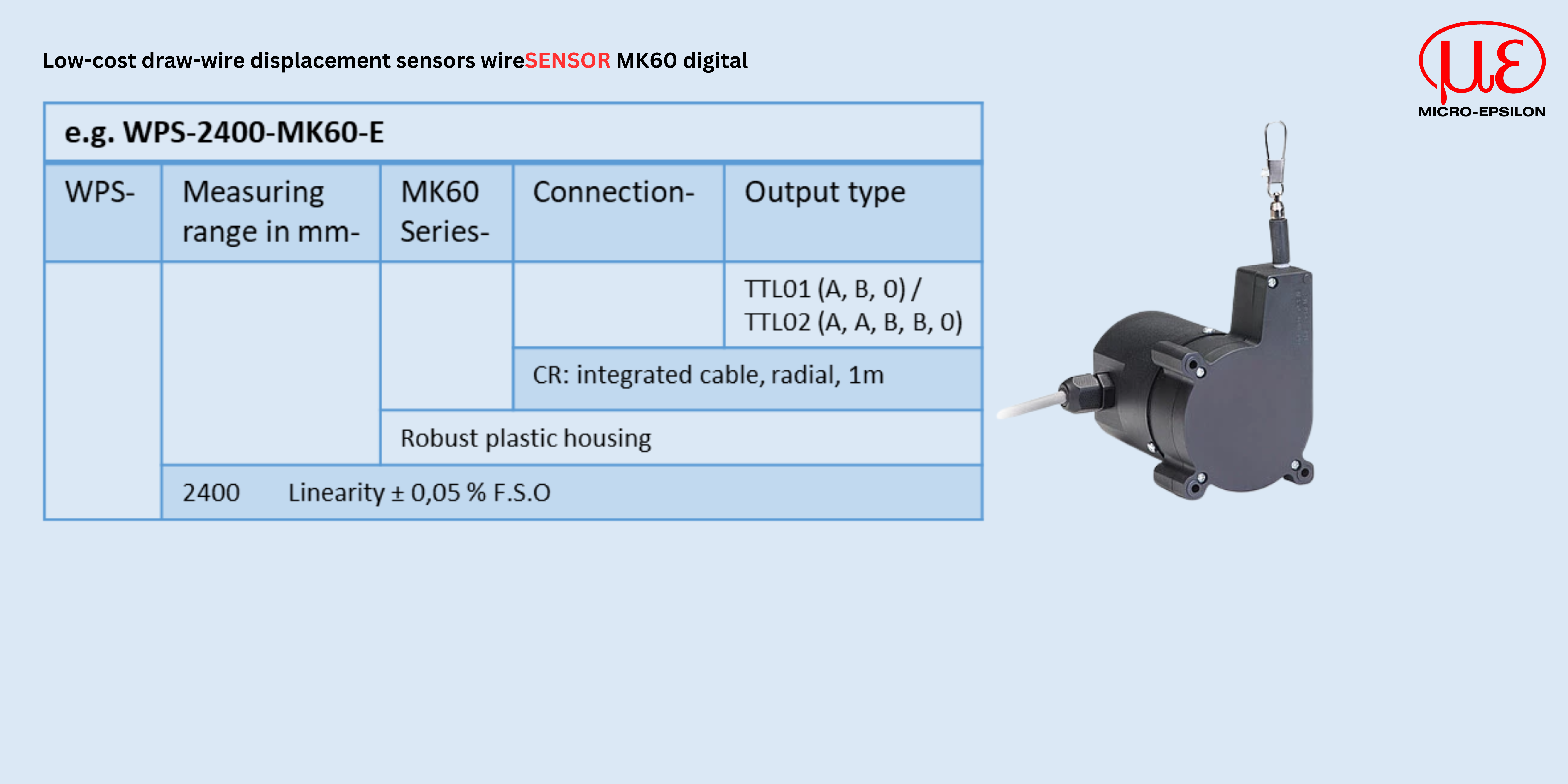
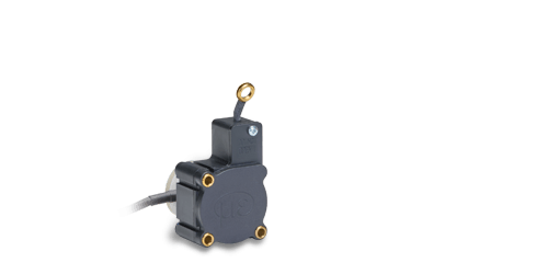
wireSENSOR WPS-MK60 digital
|
|
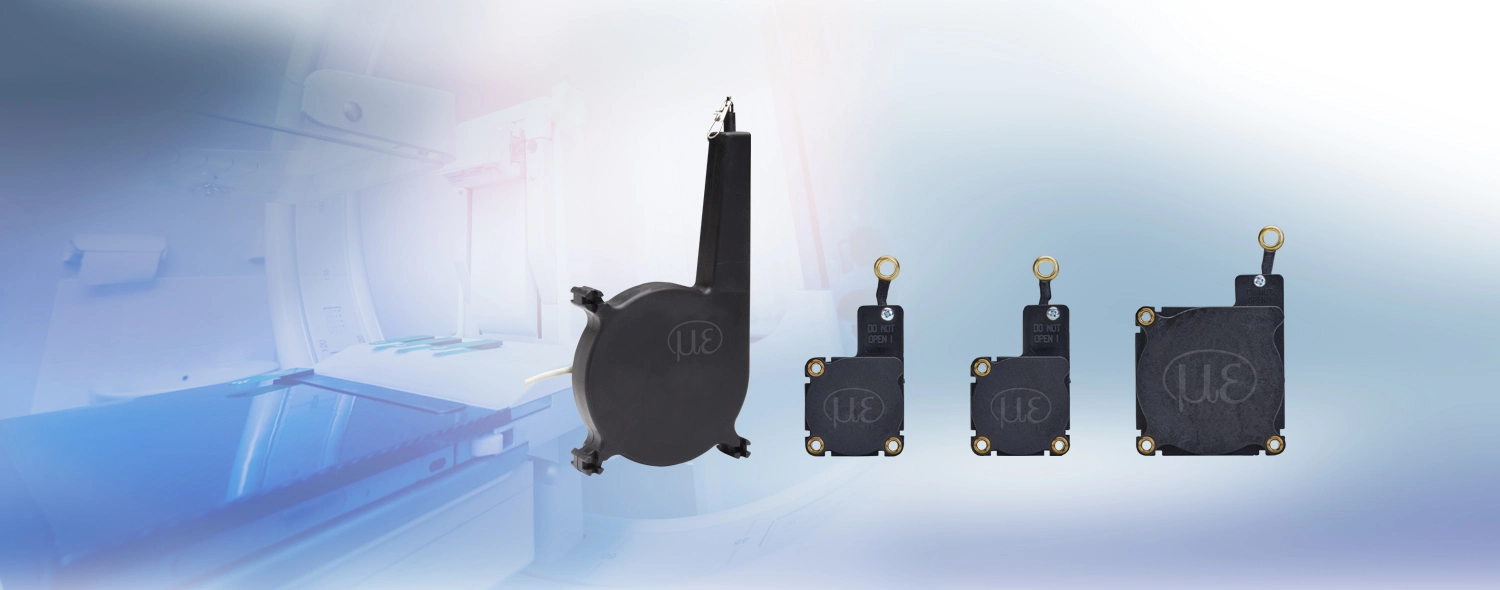
The miniature draw-wire sensors of the MK series are specially designed for use in high-volume production. Due to the favorable price and the compact size of the sensor, new potential designs and cost optimization are the benefits to the user.
|
|
|
|
| |
| |
|
| |
|
|
|
|
|
|
| |
|
|
| |
 |
|
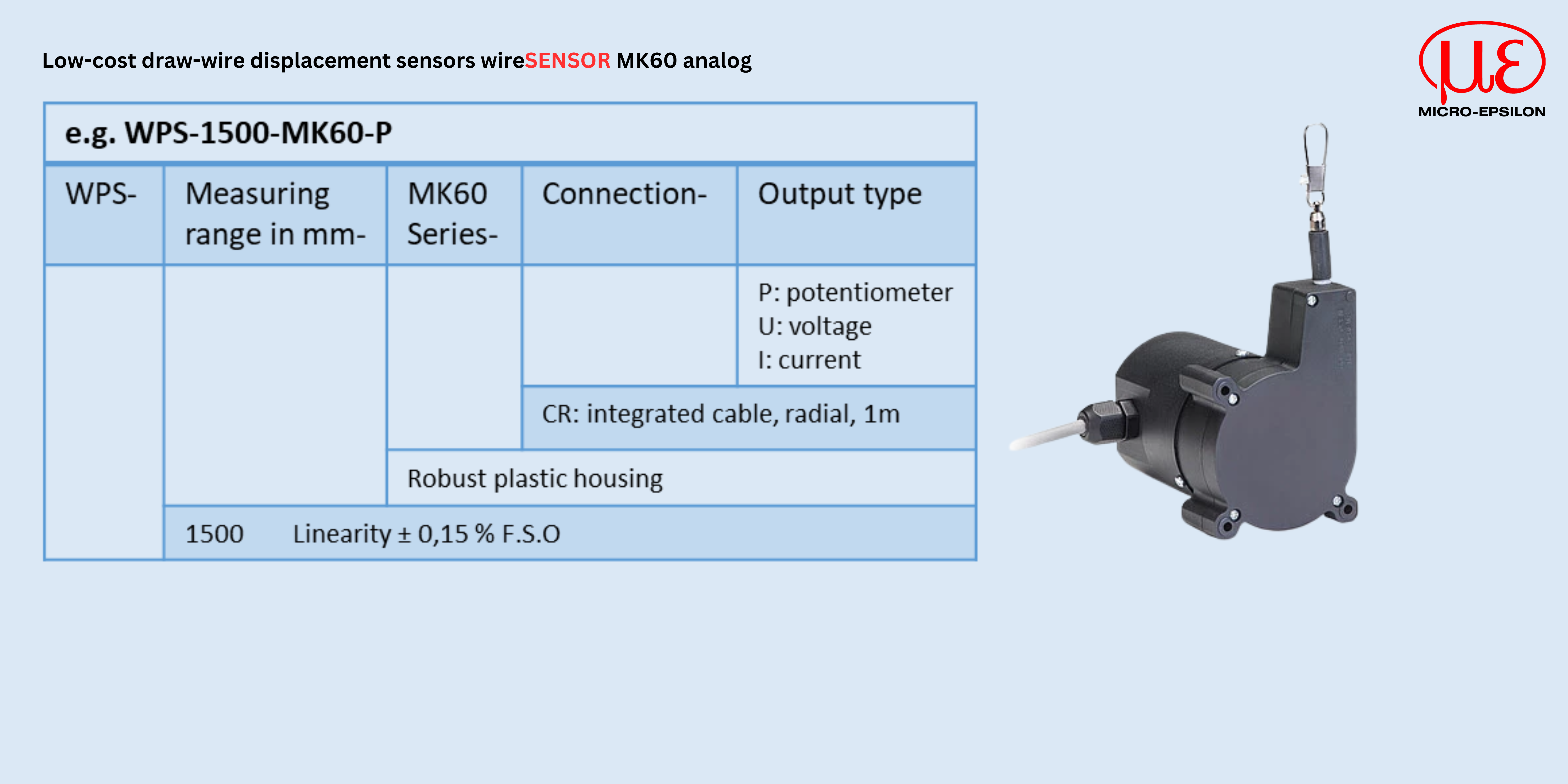
wireSENSOR WPS-MK60 analog
|
|
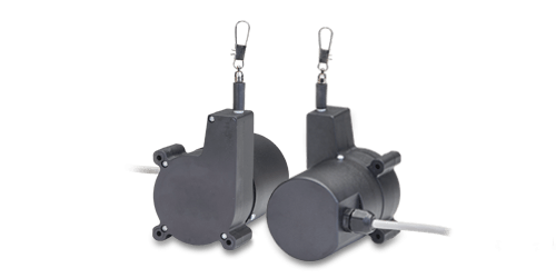
The miniature draw-wire sensors of the MK series are specially designed for use in high-volume production. Due to the favorable price and the compact size of the sensor, new potential designs and cost optimization are the benefits to the user.
|
|
|
|
| |
| |
|
| |
|
|
|
|
|
|
| |
|
|
| |
 |
|
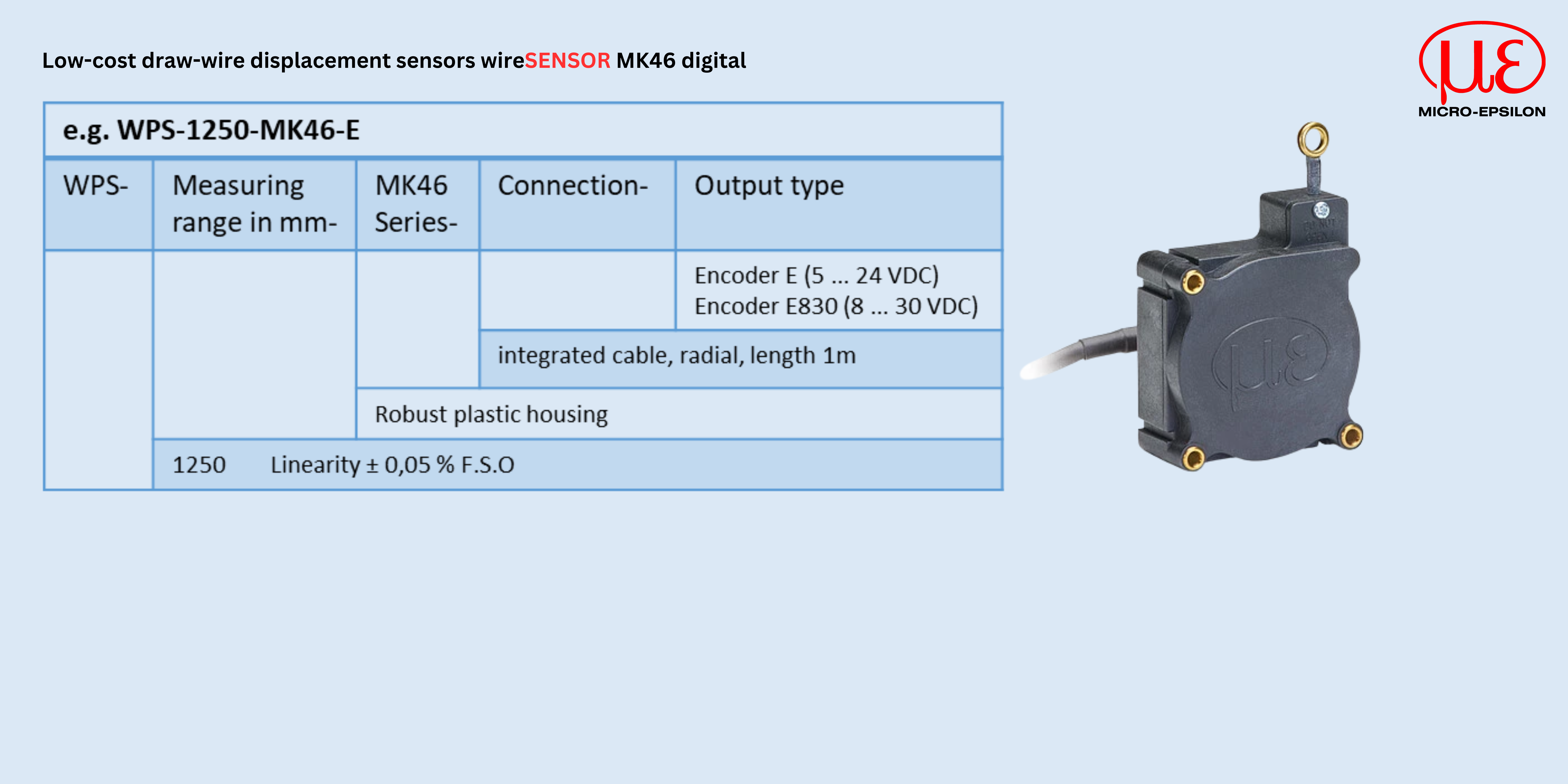
wireSENSOR WPS-MK46 digital
|
|
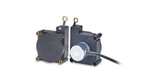
The miniature draw-wire sensors of the MK series are specially designed for use in high-volume production. Due to the favorable price and the compact size of the sensor, new potential designs and cost optimization are the benefits to the user.
|
|
|
|
| |
| |
|
| |
|
|
|
|
|
|
| |
|
|
| |
 |
|
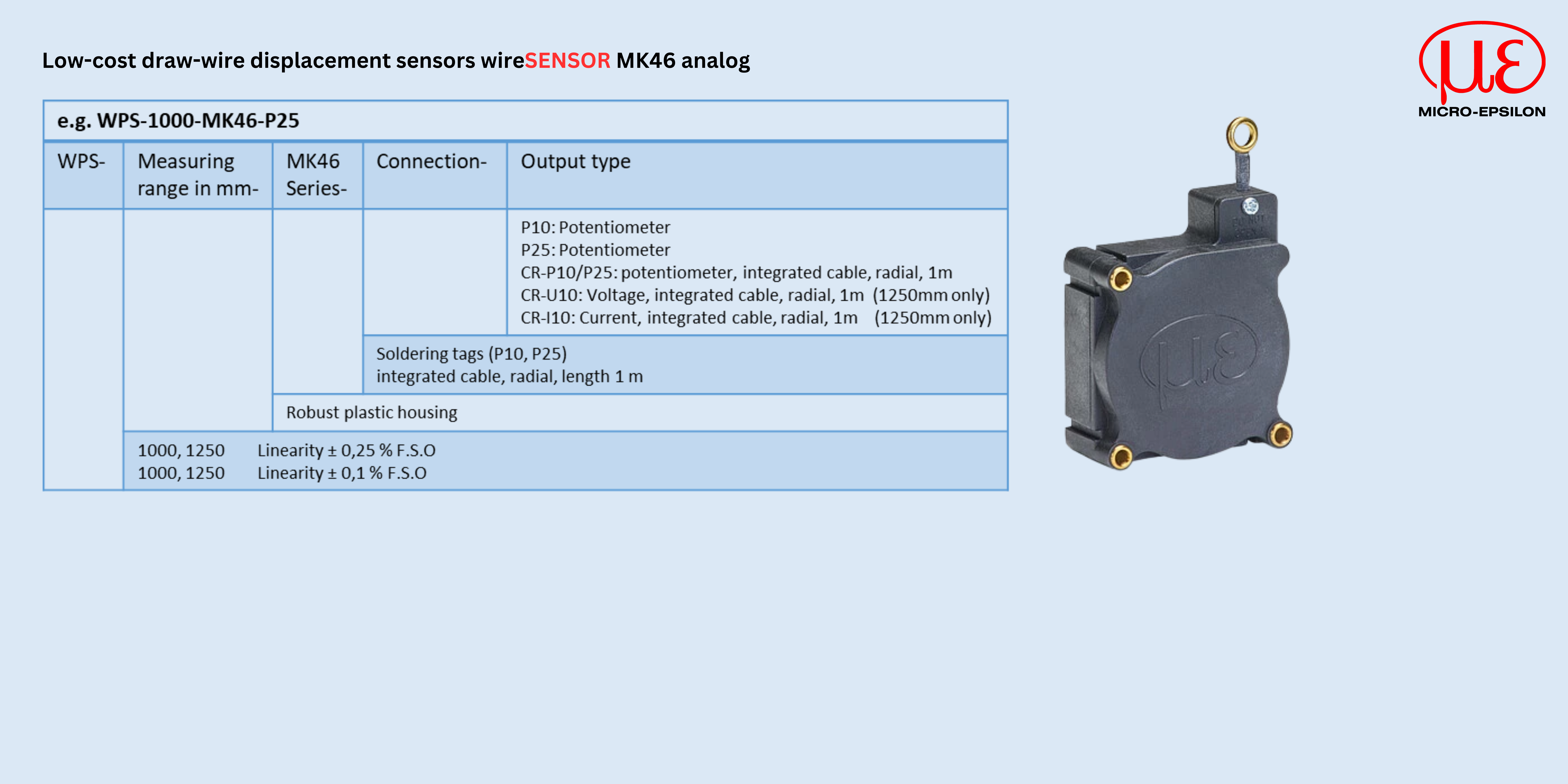
wireSENSOR WPS-MK46 analog
|
|
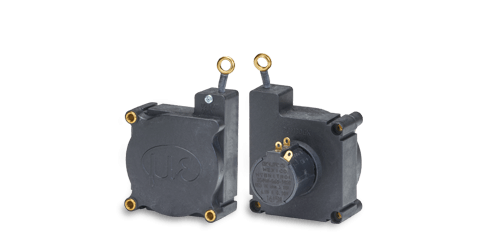
The miniature draw-wire sensors of the MK series are specially designed for use in high-volume production. Due to the favorable price and the compact size of the sensor, new potential designs and cost optimization are the benefits to the user.
|
|
|
|
| |
| |
|
| |
|
|
|
|
|
|
| |
|
|
| |
 |
| |
wireSENSOR WPS-MK30 digital
|
|
The miniature draw-wire sensors of the MK series are specially designed for use in high-volume production. Due to the favorable price and the compact size of the sensor, new potential designs and cost optimization are the benefits to the user.
|
|
|
|
| |
| |
|


 Measuring range (mm): 2,400
