 |
|
|
|
|
|
|
Active capacitive measuring system with analog output – capaNCDT 6114
|
|
|
|
The capacitive capaNCDT 6114 measuring system offers high application versatility due to its long signal transmission path. With a robust and up to 15 m long cable, the system is ideally suited to drag chains and robots. Even with movements of the sensor cable, precise measurement results are achieved with the highest signal stability. The capaNCDT 6114 provides an analog output of 0 ... 10V. |
|
|
Active capacitive measuring system with RS485 interface – capaNCDT 6124
|
|
|
|
The capacitive capaNCDT 6124 measuring system offers high application versatility due to its long signal transmission path. With a robust and up to 15 m long cable, the system is ideally suited to drag chains and robots. Even with movements of the sensor cable, precise measurement results are achieved with the highest signal stability. The capaNCDT 6124 measuring system provides an analog output via a digital RS485 interface. |
|
|
|
|
 |
|
|
|
|
|
|
Industrial-grade, capacitive controller with voltage output – DT6110/IP controller
|
|
|
|
Protected to IP68, the DT6110/IP capacitive controller is designed for measurement tasks in industrial environments. The DT6110/IP controller is available with either a voltage or current output, and can also be used in confined spaces due to its compact design. |
|
|
Industrial-grade, capacitive controller with RS485 interface – DT6120/IP controller
|
|
|
|
Classified to IP68, the DT6120/IP capacitive controller is designed for measurement tasks in industrial applications. In addition to either a voltage or current output, the DT6120/IP controller offers an RS485 interface. Due to its compact design, the controller can also be used in confined spaces. |
|
|
|
|
 |
|
|
|
|
|
|
Compact capacitive controller with high resolution – DT6110 controller
|
|
|
|
The capacitive DT6110 controller is the entry model for high resolution, capacitive displacement measurement. Due to its extremely compact size, the controller can also be integrated into restricted installation spaces. The DT6110 controller is compatible with all sensors and cables of the capaNCDT series. The DT6110/ECL2 controller provides an extended cable length. |
|
|
Capacitive controller for dynamic measurement tasks up to 20kHz (-3dB) – DT6112 controller
|
|
|
|
The capacitive DT6112 controller is the entry model for dynamic measurement tasks. A bandwidth of up to 20kHz (-3dB) enables reliable monitoring of fast processes. The DT6112 controller is compatible with all sensors and cables of the capaNCDT series. |
|
|
Compact capacitive controller with RS485 interface – DT6120 controller
|
|
|
|
Equipped with an analog output and an RS485 interface, the capacitive DT6120 controller is the entry model for high resolution, capacitive displacement measurement. Due to its extremely compact size, the controller can also be integrated into restricted installation spaces. The DT6120 controller is compatible with all sensors and cables of the capaNCDT series. |
|
|
|
|
 |
| |
Highly dynamic laser sensor up to 75 kHz
|
| |
|
|
| |
 |
| |
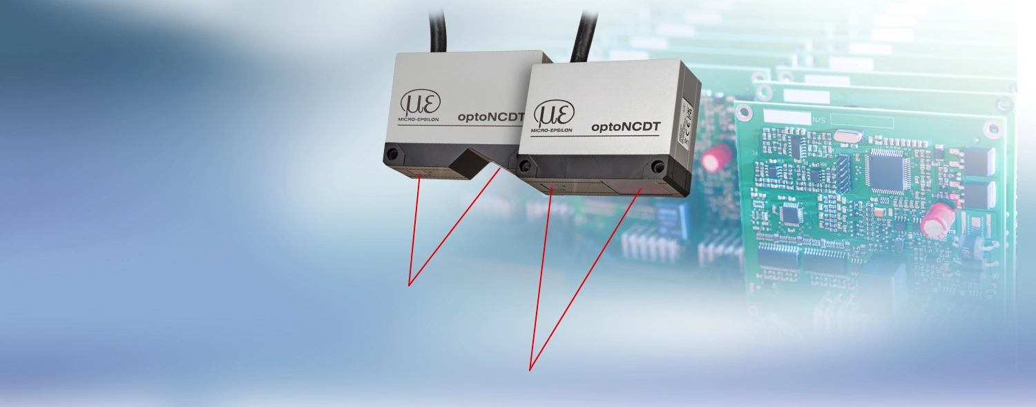
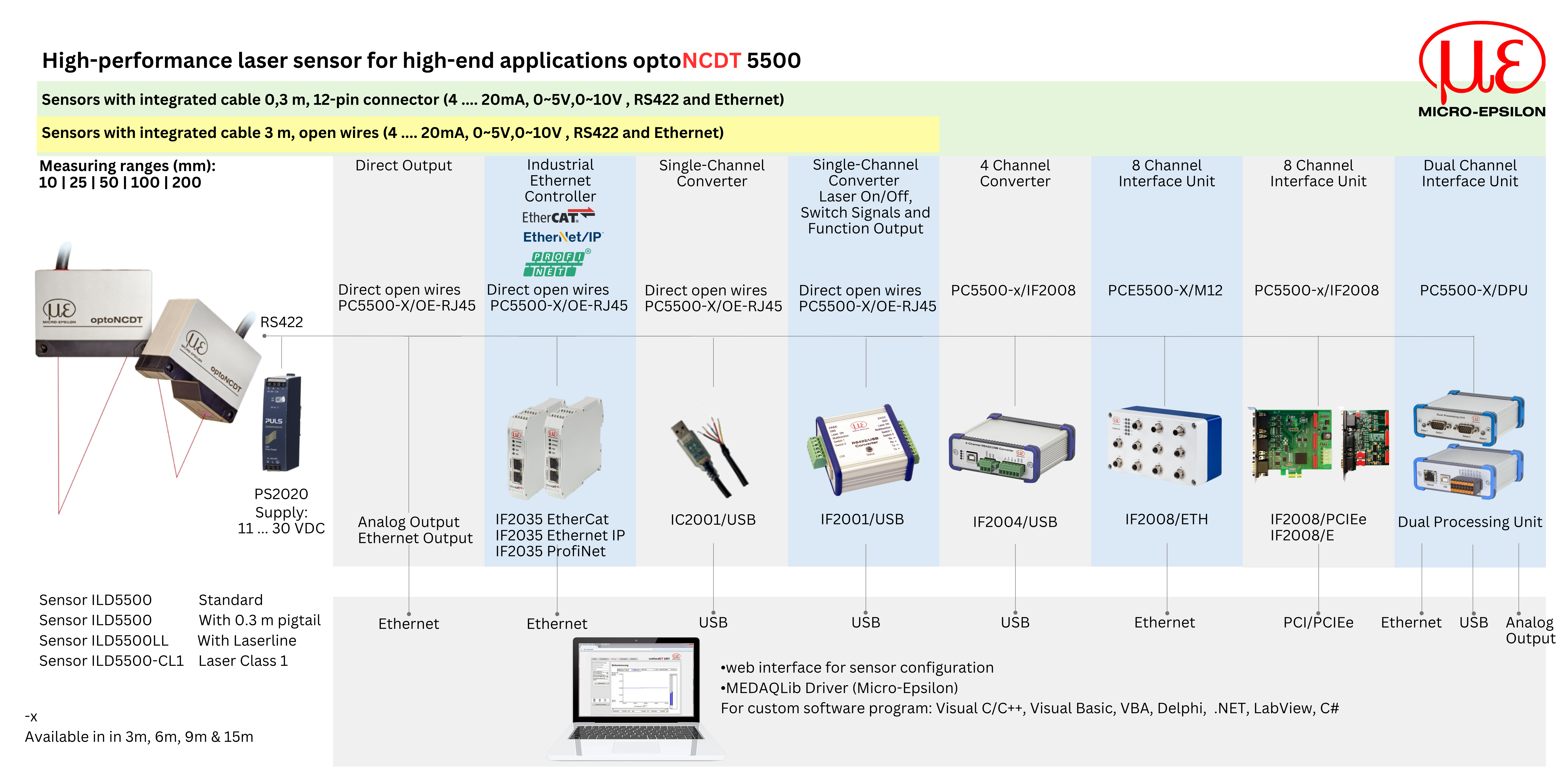
| The optoNCDT 5500 laser sensors set new standards in high-precision laser distance measurement. With submicron precision and an impressive measuring rate up to 75 kHz, the sensors are perfect for dynamic measurements of displacement, distance, vibration and position. Due to its integrated controller, the compact sensor does not require any external control units and can be easily integrated even in confined installation spaces. Maximum performance in the smallest of spaces - the optoNCDT 5500 series. |
| |
|
|
| |
Versatile use
|
| |
| The optoNCDT 5500 sensors are available with different measuring ranges. In addition to the standard measuring range, an extended measuring range can be used, which significantly expands the fields of use. With IP67 protection and high resistance to ambient light, the laser sensor can also be used in challenging environmental conditions. |
| |
Highest performance: A new class of laser triangulation sensors
|
| |
|
The optoNCDT 5500 from Micro-Epsilon represents the latest performance class among laser triangulation sensors. With its increased measuring rate of up to 75 kHz, the sensor is ideal for highly dynamic measurement tasks. This laser sensor delivers extremely precise measurement results, even on rapidly changing and poorly reflective surfaces. Its high repeatability enables measurements with submicron precision.
|
|
 |
|
| |
Advanced Surface Compensation - The intelligent exposure control for all surfaces
|
| |
|
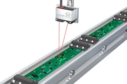
The optoNCDT 5500 is equipped with an intelligent surface control feature. New algorithms enable fast exposure control and therefore stable measurement results on surfaces where changing reflections occur. In addition, the sensor is extremely resistant to ambient light and can also be used in strongly illuminated environments. The new algorithms compensate for ambient light up to 50,000 lux.
|
|
 |
|
| |
Simple mounting and initial operation
|
| |
|
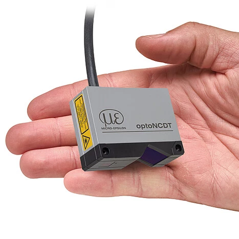
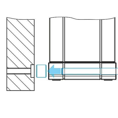
It is not necessary to align the sensor due to patented, repeatable mounting using mounting sleeves. This enables both easy sensor replacement and even higher precision in solving measurement tasks. Due to its small dimensions and the integrated controller, the laser sensor can also be installed in confined spaces. A web interface with ready-made presets makes the sensor immediately ready for use. The ILD5500 is more compact than its predecessor ILD2300. To enable a seamless changeover, Micro-Epsilon offers an adapter plate for a quick switch from ILD2300 to ILD5500.
|
|
 |
|
| |
 |
|
 |
|
 |
| |
|
|
|
|
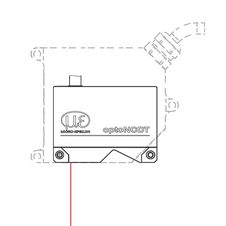
| Space-saving design, no external controller required |
|
Adapter plates for replacing optoNCDT 2300 sensors |
|
Patented mounting concept for repeatable fastening |
|
| |
Applications
|
| |
 |
|
 |
|
 |
| |
|
|
|
|
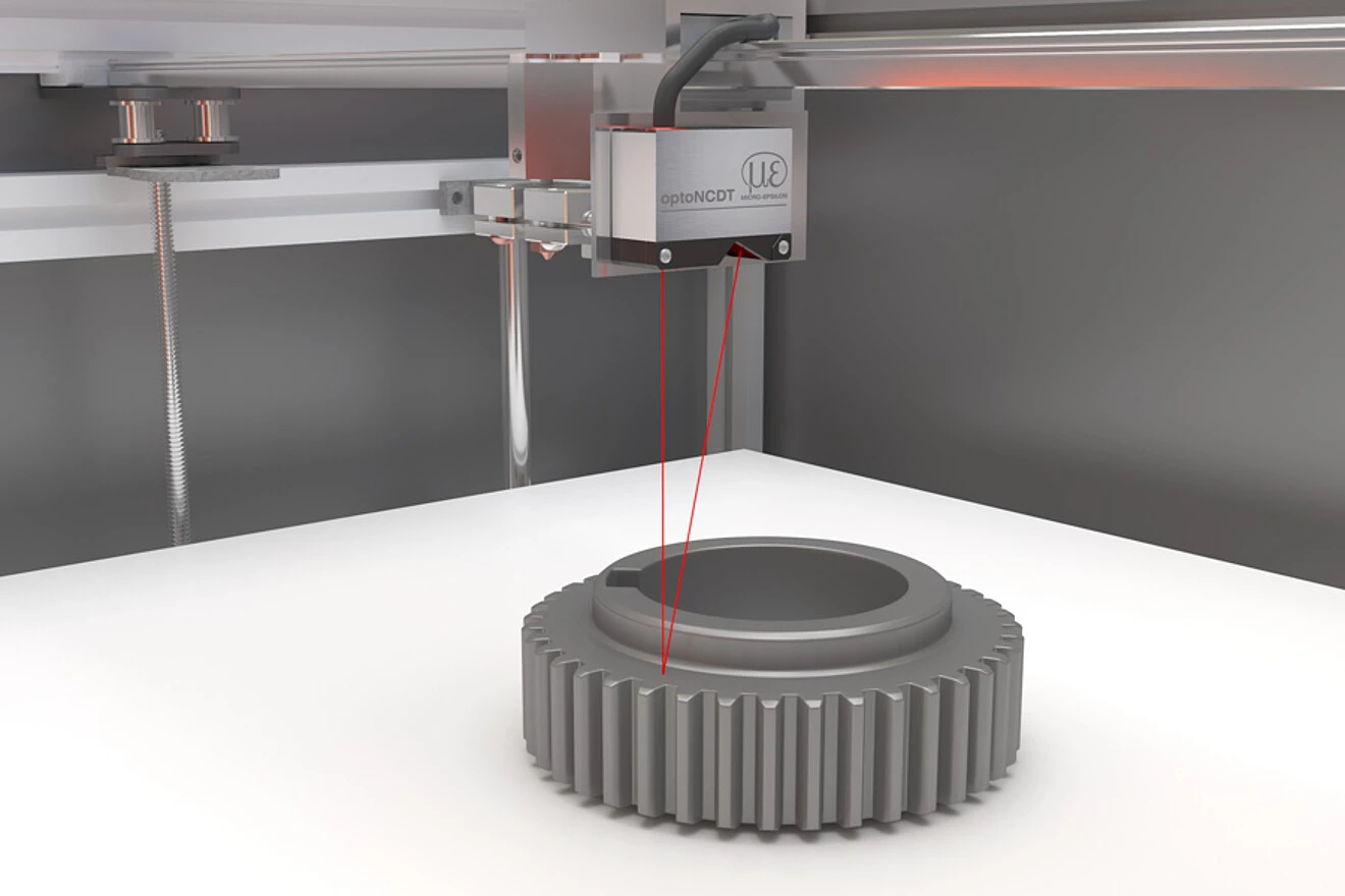
| Positioning the print head in additive manufacturing |
|
Distance monitoring on black rubber |
|
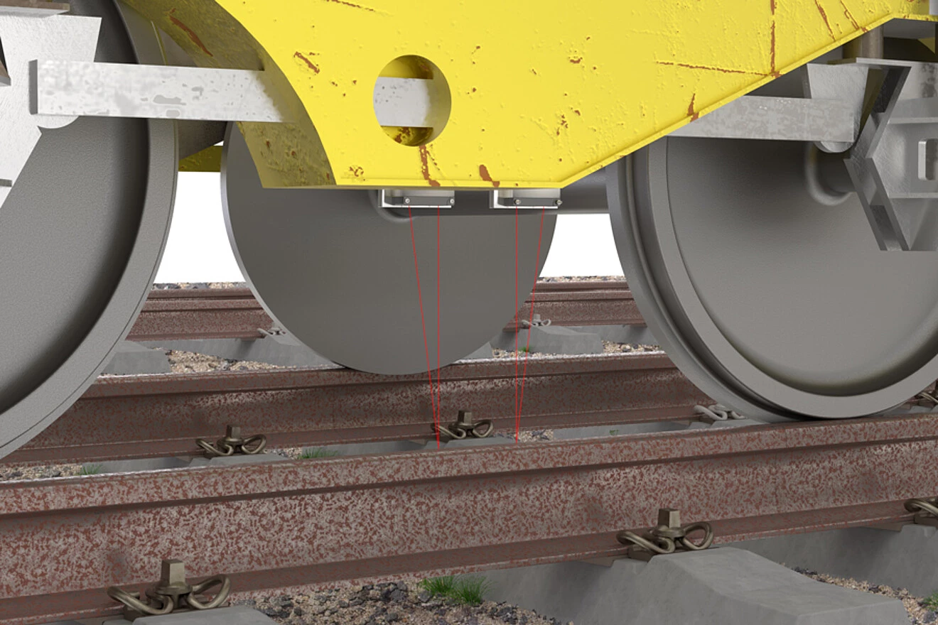
Wear test on rails |
|
| |
| |
 |
| |
Powerful laser distance sensor
|
| |
|
|
| |
 |
|
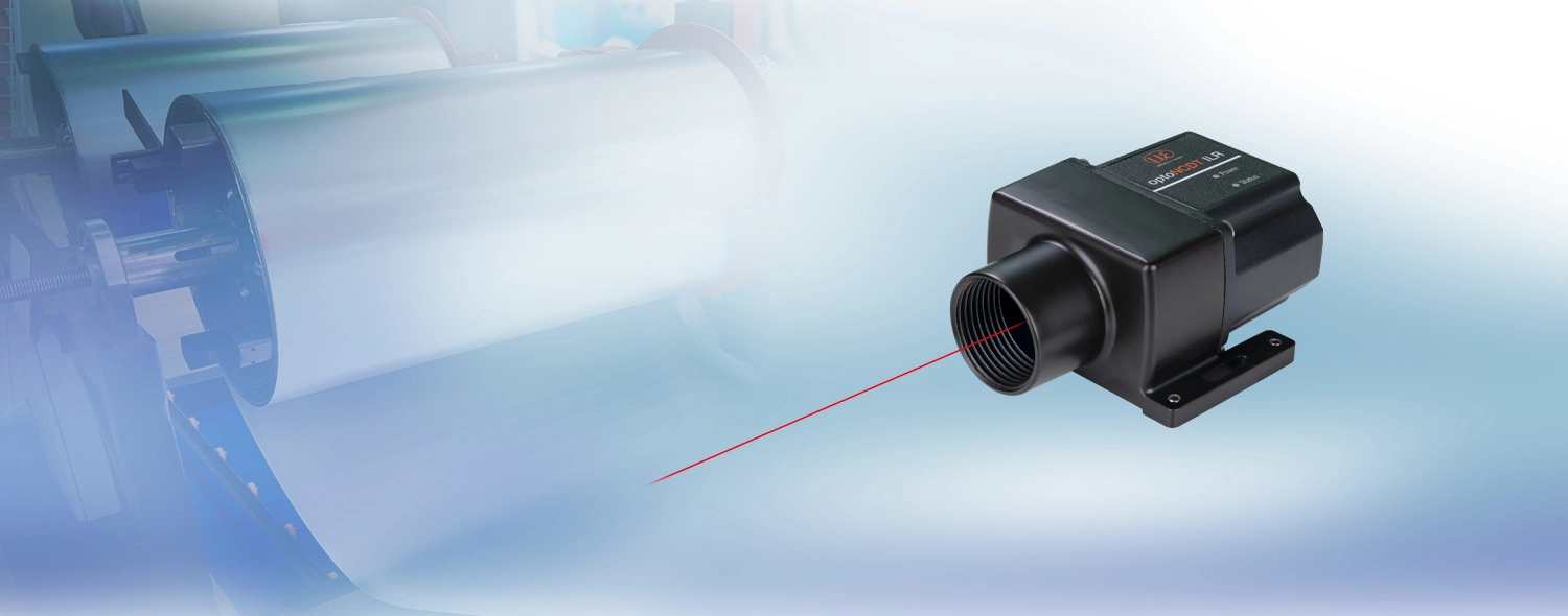
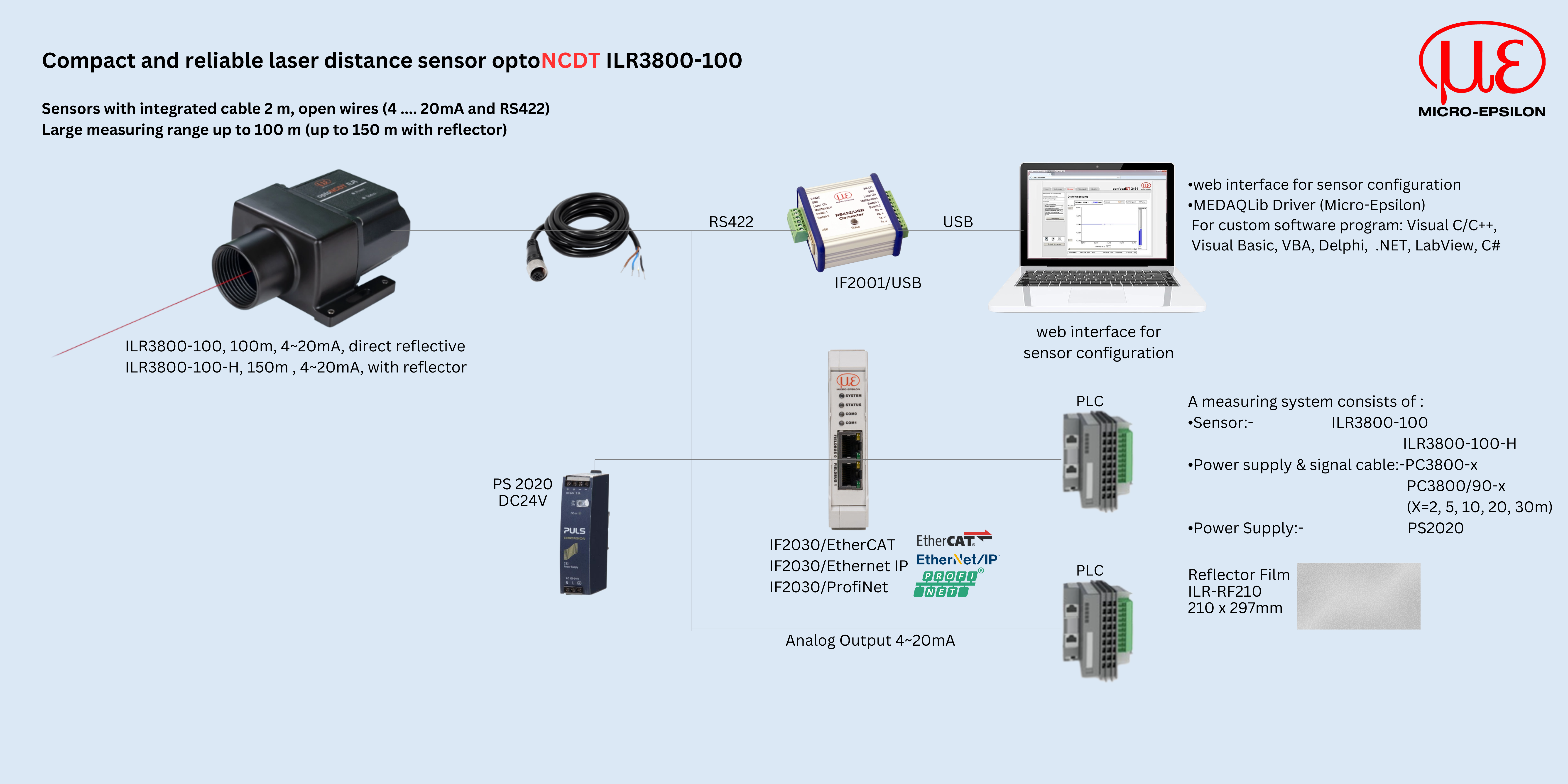
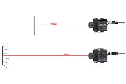
| The optoNCDT ILR3800-100 laser distance sensor stands out in particular due to its high performance in a compact design. It is designed for precise distance measurements in industrial environments. Distance measurements up to 100 m are possible. With reflector even up to 150 m. The integrated AUTO measurement mode enables reliable measurement even on dark, partly reflecting and remote measuring objects. Thanks to the very high signal stability, ILR3800-100 sensors can be used for distance measurements on numerous surfaces. |
|
|
|
| |
Compact sensor design for versatile measurement tasks
|
| |
 |
| |
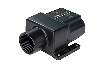
| The laser distance sensor impresses with very high signal stability and is, among other things, used in logistics and automation technology, the metals industry and production monitoring. The robust aluminum housing and low weight allow easy integration into numerous industrial environments. |
| |
|
|
| |
The ILR3800-100 detects distances up to 100 m (without reflector), with reflector up to 150 m. This means the sensor is suitable for measurements tasks in logistics, factory and plant automation, as well as in drone applications for distance measurements from the air.
|
| |
New ILR3800-100-H with integrated heating for outdoor use
|
| |
|
The ILR3800-100-H model has an integrated heating and cooling element that enables operation in the temperature range of -40 to +55 °C. This makes the sensor perfectly suitable for permanent outdoor use.
|
|
 |
|
| |
Mounting plate as optional accessory
|
| |
|
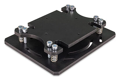
You can easily replace the previous ILR2250-100 model with the new ILR3800-100 laser distance sensor. The mounting plate makes the changeover quick and easy.
|
|
 |
|
| |
Workpiece positioning in CNC machining
|
| |
|
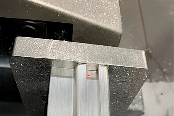
Due to its robust and compact design, the powerful optoNCDT ILR3800-100 laser distance sensor is ideal for monitoring the position of large measuring objects such as rails. Over a total length of up to 3 m, the entire workpiece is detected by ten laser sensors. Due to the high accuracy and signal stability of the sensor, exact positioning on the clamping system of the CNC machine tool is possible. This ensures precise processing of the rails and reduces the error rate to a minimum.
|
|
 |
|
| |
|
|
| |
| |
|