


 |
||||||||||||||||||||||||||||||||||||
| FUTEK’s calibration department performs testing with a focus on expediency, reliability and rigorous attention to detail. | ||||||||||||||||||||||||||||||||||||
Our calibration services include:
|
||||||||||||||||||||||||||||||||||||
Our unique customer benefits include:
|
||||||||||||||||||||||||||||||||||||
Examples of the calibration certificates we offer: |
||||||||||||||||||||||||||||||||||||
| When you receive your calibration certificate, do not discard it because it contains pertinent information relating to the sensor(s) you purchased. | ||||||||||||||||||||||||||||||||||||
 |
||||||||||||||||||||||||||||||||||||
Our wide range of calibrationsWe offer our customers the unique ability to select the exact calibration direction outlined per their application's requirements, including: |
||||||||||||||||||||||||||||||||||||

Sensors will be calibrated in tension

Sensors will be calibrated in compression

Sensors will be calibrated in both tension and compression

Sensors will be calibrated at pressure
|
||||||||||||||||||||||||||||||||||||

Sensors will be calibrated in clockwise direction

Sensors will be calibrated in counter-clockwise direction

Sensors will be calibrated in both clockwise and counter-clockwise direction

Sensors will be calibrated in a vacuum
|
||||||||||||||||||||||||||||||||||||
Due for recalibration?Because our products are used in critical applications that require exact specifications, we have created a recalibration program that continuously supports our customers needs for verification and alignment. We also offer recalibration services to customers who have purchased test and measurement products from the following manufacturers:
|
||||||||||||||||||||||||||||||||||||
General calibration services frequently asked questions (FAQ)Why is it important to calibrate load cell and torque sensors?Load Cell Calibration Service is an adjustment or set of corrections that are performed on a load cell, or instrument (amplifier), to make that the sensor operates as accurately, or error-free, as possible. Every sensor is prone to measurement errors. These structural uncertainties are simply the algebraic difference between the value indicated by the sensor output versus the actual value of the measured variable, or, known reference loads, in order to generate the load cell calibration curve. Every sensor is prone to measurement errors. These structural uncertainties are the simply algebraic difference between the value that is indicated by the sensor output versus the actual value of the measured variable, or known reference loads. Measurement errors can be caused by many factors:
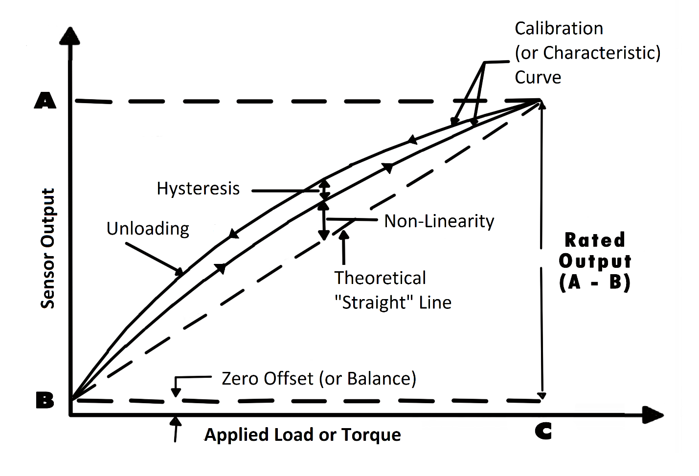 Figure 1: Load Cell Calibration Curve. Each force sensor has a "characteristic curve" or a "calibration curve", which defines the sensor's response to an input. During a regular calibration using the load cell calibration machine, we check the sensor's zero offset and linearity by comparing the sensor output under reference weights and adjusting the sensor response to an ideal linear output. We also check hysteresis, repeatability and temperature shift when customers request it for some critical force measurement applications. For more information about calibration, please refer to our Force Sensor Calibration FAQ Page. If you have further questions about calibration terms and definitions, please refer to our Force Sensor Calibration Terms Glossary. How often should a load cell be recalibrated?As load cells are exposed to continuous usage, aging, output drift, overload, improper handling, FUTEK highly recommends a yearly recalibration interval. Frequent recalibration helps confirm whether the sensor maintained its accuracy over time and provides a load cell recalibration certificate to show the sensor still meets specifications. However, when the sensor is used in critical applications and harsh environments, load cells may require even more frequent calibrations. Please consult with our Technical Support team, who will help you evaluate the most economical calibration service interval for your force sensor. What is a system calibration (sensor plus amplifier/instrument)?A system calibration provides the signature of the performance of the sensor and instrument together ("calibration curve") and ensures that the combination of the results meet specifications. A force measurement system usually encompasses the force sensor, instrument or signal conditioner (amplifier electronics), cabling, and connectors. Full system calibration ensures that the whole system is performing accurately as expected. Check out below a video on the "Benefits of System Calibration": |
||||||||||||||||||||||||||||||||||||
|
|
||||||||||||||||||||||||||||||||||||
|
Choosing complete system calibration allows you to start using your force measurement solution out of the box. A system calibration creates a plug & play solution where all connectors, cables, and instrument settings are taken care of. As an A2LA certified calibration lab, FUTEK offers full system calibration for sensors with digital displays, amplifiers, and/or USB solutions, and use calibration procedures in compliance with ISO 17025 standards. FUTEK's certification includes accreditation to ANSI/NCSL Z540-1. What are the different types of load cell calibration procedures?One-point calibration
Two-point calibration
Five-points calibration (multi-point curve fitting)
As most of the force sensors are paired with a readout display or signal conditioner to form a turnkey force measurement system, the instrumentation should always be hooked up with the sensor and be calibrated together as a system using standard equipements of the torque sensor calibration lab. That said, consider for example a 50 lbs LSB205 Miniature S-beam Load cell paired with an IAA200 4-20mA Current output amplifier and a 10ft long cable. When requested by the customer, the five-point output readings would be taken when the sensor is subjected to loads of 0 (no load), 10 lbs, 20 lbs, 30 lbs, 40 lbs and 50 lbs upward scale and downward scale. |
||||||||||||||||||||||||||||||||||||
|
||||||||||||||||||||||||||||||||||||
|
Table 1: Load Cell 5-Points Calibration and Multi-Point fitting. Depending on the application requirements, this procedure is repeated twice or multiple times. The difference in the outputs is utilized to calculate the non-repeatability (or repeatability) and linearity (accuracy). We are frequently questioned on how to calibrate a torque wrench. This can be accomplished by utilizing FUTEK’s TDF Torque Sensor as a torque wrench calibration tool to verify the precision of a torque wrench. |
||||||||||||||||||||||||||||||||||||
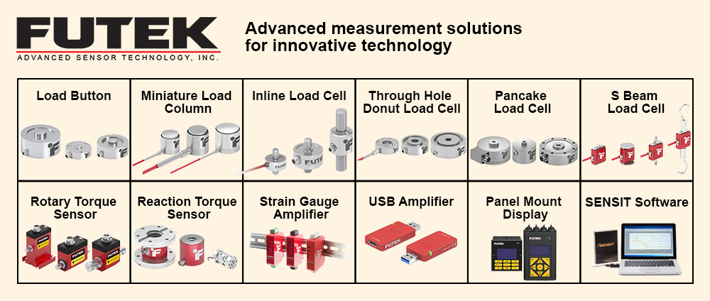
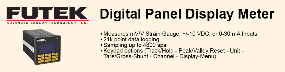
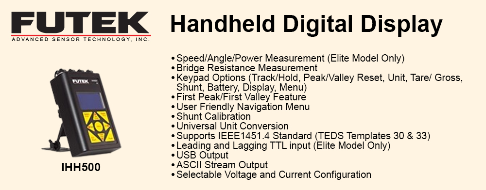
 Full-system calibration for sensors with FUTEK and non-FUTEK digital displays, amplifiers and USB solutions