


 |
||||||||||||||
|
||||||||||||||
What is colorSENSOR measuring principle? |
||||||||||||||
|
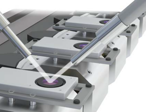
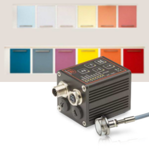
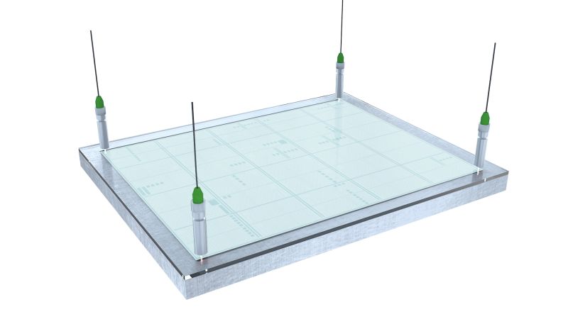
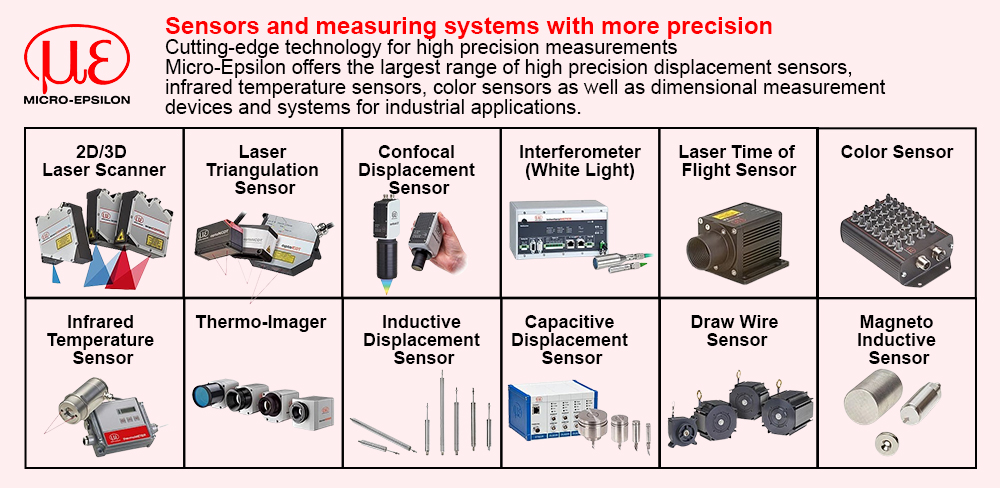
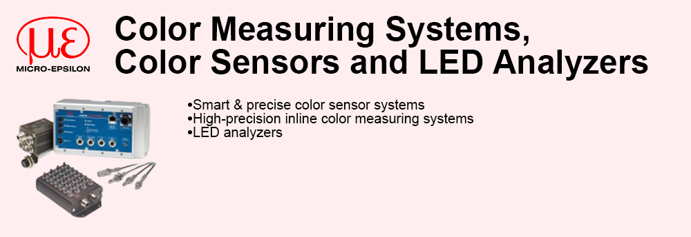
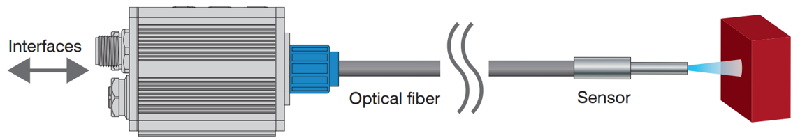
In the field of color inspection, a measurement channel usually consists of a sensor (also referred to as probe head or sensor head) and a controller (evaluation unit). The surface to be measured is illuminated via the sensor cable (fiber optics). The light (color) reflected by the surface is detected by the sensor and evaluated by the controller. The sensors have different measuring geometries and can optionally be extended by mountable lenses for focusing or to achieve larger measurement distances. Models with integrated controller of the OT series are also available for large measurement distances. |
||||||||||||||
 |
||||||||||||||
|
The specimen is illuminated with homogeneous, white light from an LED. A CFS sensor is used to project a point of illumination onto the surface to be inspected. The light is reflected diffusely at a specified angle and transmitted by the same sensor to a perceptive True Color receiver (XYZ) where it is analyzed.
The three wavelength ranges, i.e.  X = long wave, Y = medium wave and Z = short wave light portions X = long wave, Y = medium wave and Z = short wave light portionsfrom the specimen are used to determine the diffuse color reflections and thereby transformed into a selected color space. These color values are calculated according to the procedure described in DIN 5033. The transformed values (colors), are stored in the controller and continuously compared to the current color. When the colors are all within the entered tolerance range, a recognition signal is sent to the digital switching outputs and the keypad indicators. This process allows storage of multiple colors in various color spaces. In the same manner, the color values and the recognized color are output as data protocol via the available interfaces as required. |
||||||||||||||
Color Spaces |
||||||||||||||
|
With the colorSENSOR CFO you can measure the following color spaces: XYZ, xyY, L*a*b*, L+u*v*, L*u‘v‘. |
||||||||||||||
Color Tolerance Models |
||||||||||||||
|
Relative color measurement is often referred to as color inspection. The color of the measuring object and the reference sample is detected with the same sensor and the color distance (Delta Erel) is evaluated based on the difference of the values. Note: The color distance between target and reference sample is determined with the same sensor (Delta Erel). |
||||||||||||||
|
The CFO controller works with a relative color measurement and thus with different tolerance models. The permissible color distance for the color to be controlled is stored in a tolerance model. If the measured value is outside the tolerance, the CFO controller outputs the switching output for Color not recognized. If the measured value is within the tolerance, the corresponding output for the detected color is signaled. |
||||||||||||||
|
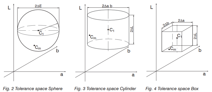
The system can be set to the distance models Sphere (∆E), Cylinder (∆L; ∆ab), Box (cuboid, ∆L; ∆a; ∆b) and Classify. These models form a tolerance space around the learned colors. |
||||||||||||||
 |
||||||||||||||
|
C1 = learned color 1 Cm = detected color For an evaluation of color deviations, the color tolerance parameters should be based on the perception thresholds for color differences. In the Lab color space, a tolerance threshold of ∆E > 1 is frequently used for perceptible color differences. Influencing factors for setting color tolerance parameters: Required accuracy for color recognition Tolerance for reading variations. |
||||||||||||||
|
A change in the color readings for one and the same specimen can have two causes:
|
||||||||||||||
Define the color distance tolerances so that the tolerance limits are greater than the change in the readings for acceptable specimens |
||||||||||||||
|
The Sphere tolerance space or rather ∆E denotes the color distance in a color space or how far apart the colors of the target and the reference object to be compared are in the spatial model. The larger the difference between the colors, the more clearly the difference can be perceived. For the tolerance model Sphere only one value can be set, (∆E = root(∆L^2+∆a^2+∆b^2)). With this tolerance model, it is not possible to determine in which color parameter the decisive change in color is present.
If you select the tolerance space Cylinder, tolerance values are set and evaluated separately for the brightness value L and the color values a/b.
Tolerance space Cylinder is useful if higher distance variants are present during the measurement, since here the value for brightness L and the values for color a and b are assigned to separate tolerance parameters. |
||||||||||||||
|
In the Box tolerance model, separate tolerance values can be set for the L, a and b color values. This enables more precise color inspections.
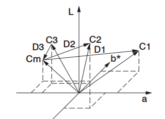
With Classify the current color readings are associated with the closest color value (shortest direct distance) saved in the color table. In this mode, classification is always accomplished regardless of the actual similarity between the selected colors.
For example, if red is the only color saved in the table, all color readings are associated with this color. In the diagram below, three colors are stored in the controller, C1...C3. Cm corresponds to the currently measured color. In the Classify mode, the controller now determines to which stored color the delta E (D1 ... D3) from Cm to C1 ... C3 is the smallest.
Since the distance D3 between Cm and C3 is the smallest, the detected color is assigned to the color output of color C3 and output by the controller. |
||||||||||||||
|
||||||||||||||