


 |
  |
|
What is a load cell?
How do you get a weight scale to give an accurate measurement of an 18-wheeler truck? What kind of instrument would you use to measure the bite force of a great white shark? These questions may seem like they apply to two very different situations, but, oddly enough, they have the same answer: by using a load cell.
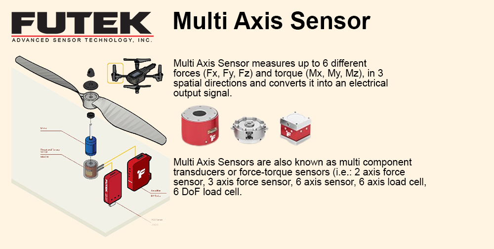
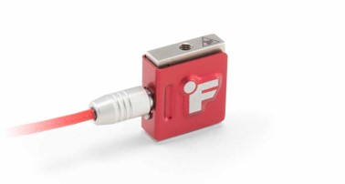
What is a loadcell sensor? A load cell, also known as a load or force transducer, is a sensor that measures applied forces. Load cells are capable of measuring both tension (force required to pull something) and compression (force required to push something). In order to measure these forces, the sensor creates an electrical output that changes depending on the amount of resistance being applied.
Force sensors are very commonplace and are incorporated into objects people use every day such as self-checkout systems at the grocery stores, or bathroom scales. But they are also used in more high-tech settings. Engineers rely on these sensors to measure rocket engine thrust, the grip force of a robotic claw, and a variety of other advanced applications.
Different types of load cells:
There are three main types of load cells that use a different way of converting the force applied into an electrical output: pneumatic load cells, hydraulic load cells, and strain gauge load cells. Within these three main categories are sub-categories.
We will focus on the most common type of load cell: strain gauge.
Strain gauge load cells are a type of resistive load cell, which includes Single Point Load cells, Button Load Cells, S-Beam Load Cells, Miniature Load Cells, Thru-Hole Load Cells, and Pancake Load Cells.
Each subsection is ideal for a different type of test. An S-beam load cell would be used in applications where tensile and compressive forces are tested. A button load cell is suitable for compression only application while a thru-hole load cell would be the best choice for measuring loads that need to be threaded (ex. bolt clamping force). |
|
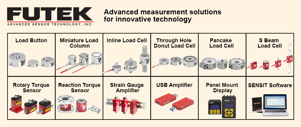
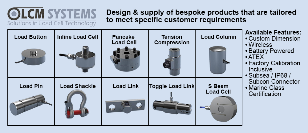
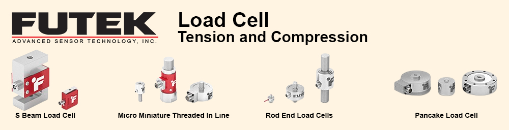
Here's an overview of the most common strain gauge load cell types:
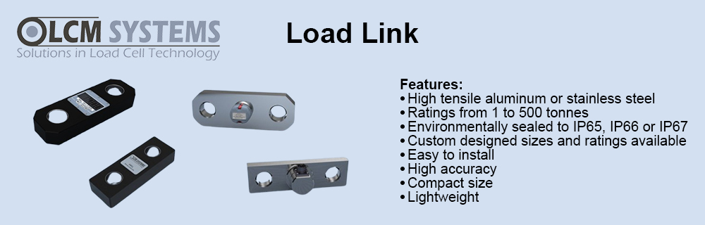
In-Line Load Cells – Most commonly referred to as an in-line load cell or a canister-style load cell with male threads. This style of sensor can be used in both tension and compression loading applications. In-line load cells offer high accuracy and high stiffness with minimal mounting clearance needed. They are great for endurance, off-center, and press applications.
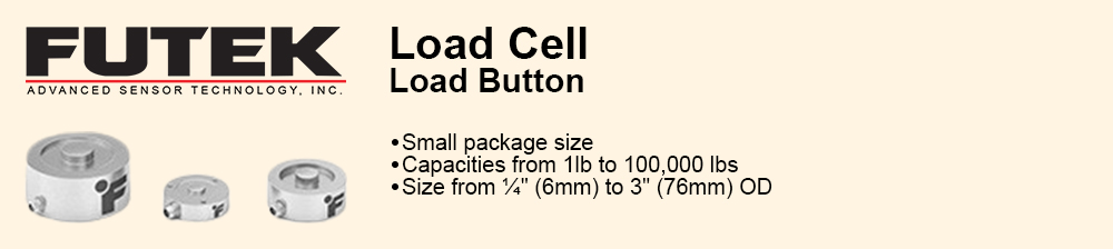
Load Button Load Cells – These load cells have a single flat, raised surface (aka a button) where the compressive force is applied. What's impressive about load buttons is their low profile design. As small as they are, they are known for their robustness and are used in fatigue applications.
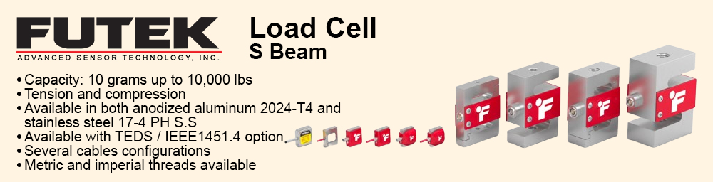
S-Beam Load Cells – With other names including Z-Beam or S-Type load cells, the S-Beam is a tension and compression sensor with female threads for mounting. Sporting high accuracy and a thin, compact profile, this load cell type is great for in-line processing and automated control feedback applications.
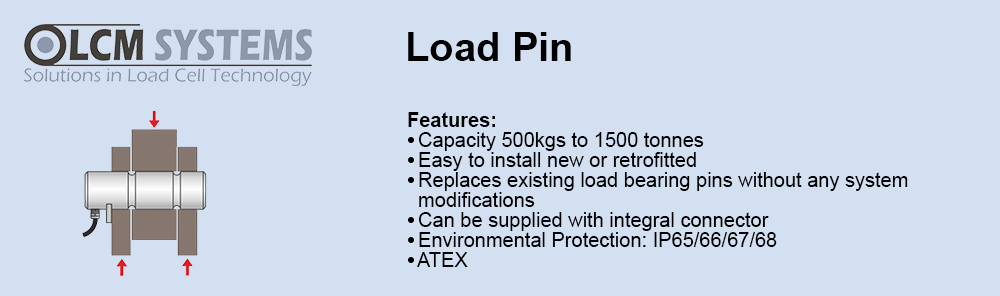
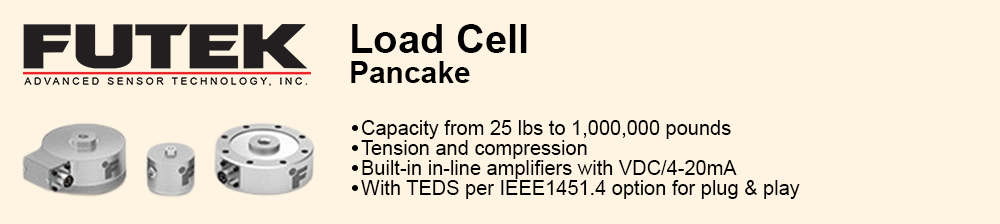
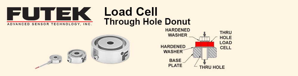
Thru-Hole Load Cells – Also known as donut load cell or washer load cell, these sensors traditionally have a smooth inner diameter used to measure compressive loads that require a rod to pass through its center. One of the primary uses of this sensor type is to measure bolt clmaping force. Pancake Load Cells – Pancake, canister-style, or universal load cells have a central threaded hole for measuring loads in either tension or compression. These load cells are used in applications needing high endurance, high fatigue life, or high-capacity in-line measurements. They are also highly resistant to off-axis loading.
Rod-End Load Cells – This load cell type offers one male thread and one female thread for mounting. The male and female thread combination is well suited in applications where you need to adapt a sensor into an existing fixture.
Single Point Load Cells - Side-mounted load cell with a single point design that is specifically made for OEM applications that require high precision or high volume production. Also known as shear beam load cells, these strain gauged-based force sensors measure tension and compression and are also known as compact parallelogram sensors or single point load cell. LRF400 is an enclosed low-capacity design suitable for applications such as high-precision milligram scale for medication. |
|
How do load cells work?
|
|
Load cells typically produce an electrical signal in millivolts that varies proportionally with the load that is being applied. However, some load cells produce digital signals or amplified analog signals that vary either in voltage, i.e. +/-10V, or current, i.e. 4-20 mA.
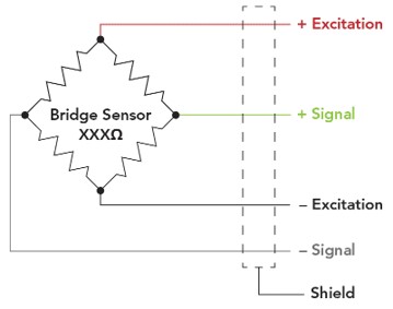
So how do strain gauge load cells produce the electrical signal? Inside, strain gauges are bonded to key structural points, and wired together into a full Wheatstone bridge. Inside each gauge is a series of fine wires. As a force is applied to the load cell, the strain gauges undergo inelastic deformation causing a change in length in the gauges' fine wires. This changes the resistance of the strain gauges, producing a measurable change in voltage across the bridge. This voltage change is a linear relationship with respect to load. |
 |
|
How do you read the sensor's signal?
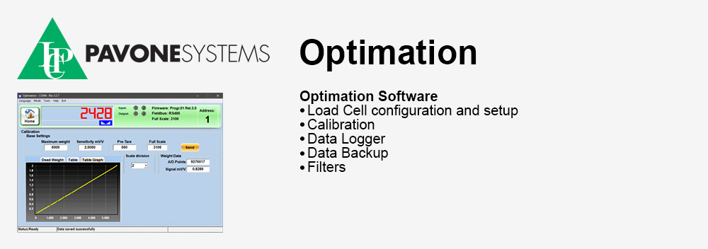
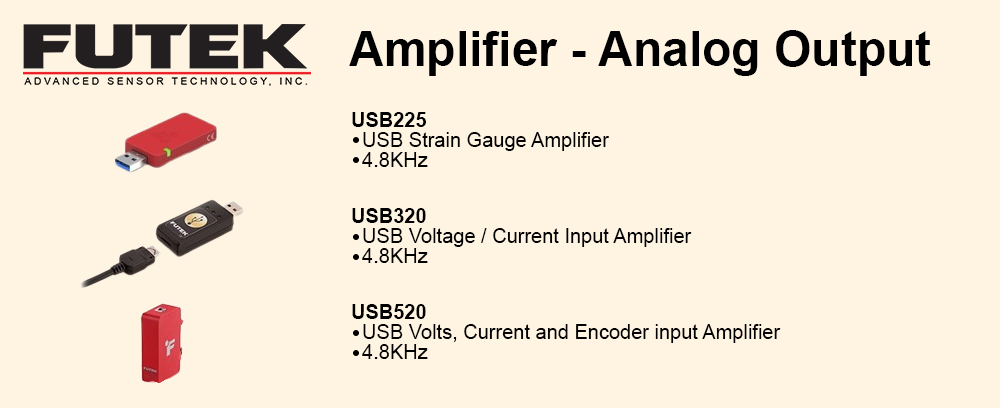
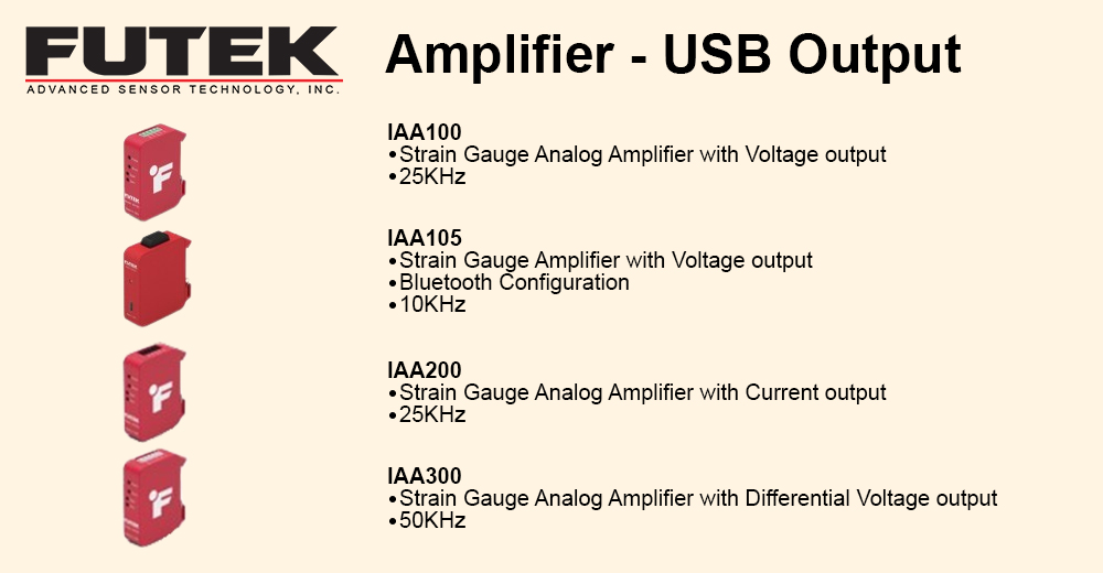
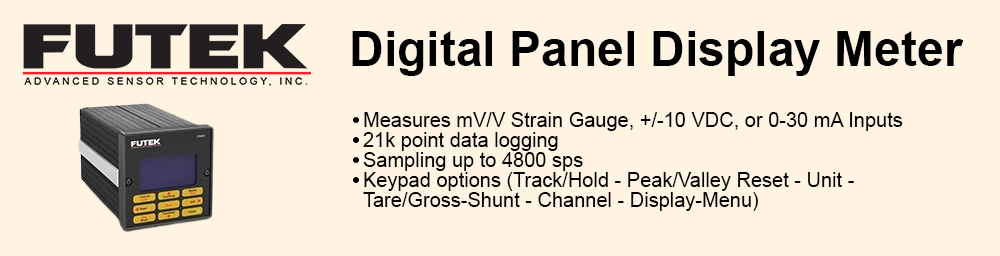
In order to read the output signal of a load cell and see the results from your testing, you can use an analog amplifier to a DAQ, PLC, or other analog display. Another option is connecting the sensor to a digital instrument such as a USB which then translates the data to a computer. Any one of these can be integrated to work with load cells, torque sensors, and pressure sensors, while providing highly accurate readings. |
|
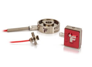
What are load cells made of?
Whether you are looking at one of our load cells, pressure sensors, or torque sensors, they are all constructed from a metal body with strain gauges wired at critical points to measure loads. We most commonly construct our sensors from aluminum or stainless steel, depending on the maximum capacity of the sensor. The strain gauges are thin metal wires bonded to a thin plastic base. These gauges are then bonded and wired onto key locations of the load cell. As the sensor is subjected to load, those locations accurately transmit the load, or strain, to the strain gauges. The wire length in the gauge then changes, altering the resistance proportionally based applied load.
The strain gauges are then wired together with balancing gauges to form a full Wheatstone bridge. With a completed bridge, an excitation voltage is applied to two opposite points of the sensor. You then measure the voltage difference between the other two points of the sensor, the signal points. When the sensor is at rest, the voltage difference between the signal points is effectively zero. As a load is applied to the sensor, the resistance across the Wheatstone bridge changes. This creates a measurable change in voltage between the two signal points which has a linear relationship to the load applied. |
|
How to choose a load cell?
We understand that choosing the right sensor is a daunting task, as there is no real industry standard on how you go about selecting one. There are also some challenges you may encounter, including finding the compatible instrumentation or requiring a custom product that would increase the product’s delivery time. We've outlined some steps to help you get started on choosing the perfect load cell for your application. Step 1 - Understand what you are measuring After you've determined your application, define what you want to measure. Do you want to measure load? This means that you want to convert input mechanical force into an electrical signal. Note that load cells are different from pressure sensors. Load cells can be used to measure surface pressure. You would use a pressure sensor if you need to measure fluid or gas pressure. Load cell applications include pressure-to-viscosity/liquid separation, automation, medical bag weighing, and many more. Here are a few examples of load cell applications that may help guide you in your selection. Step 2 - Define key characteristics Next, you should take a look at some of the characteristics that would define your needs. Do you have a static load or a dynamic load? Define the mounting type. How will you be mounting this load cell? Is it female/male thread, in-line, side mount, flange mount, thru-hole, or compression washer? What is your load direction? (Tension, compression, or both?) Step 3 - Determine your capacity requirements Define your minimum and maximum capacity requirements. Be sure to select the capacity over the maximum operating load and determine all extraneous loads and moments before selecting the capacity. Note: if the correct load is not selected, extraneous loads and moments increase combined stress which accelerates fatigue and will also affect the performance and accuracy. Most in-line sensors such as an S-Beam load cell are not designed with extraneous load and moment capabilities. For endurance or fatigue applications, try to operate at 50% or lower of the rated capacity or use a fatigue rated sensor. Step 4 - Define your size requirements Next you need to define your size requirements (width, weight, height, length, etc.) and specification requirements (output, nonlinearity, hysteresis, creep, bridge resistance, resolution, frequency response, etc.) You also should recognize if your application will be submersible or exposed to water, or will experience cryogenic or high temperatures. |
|
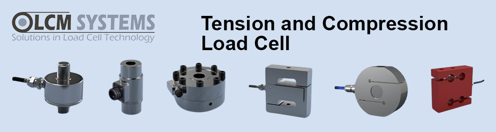
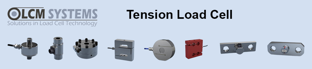
After you've followed the above steps, you'll have a better idea of what load cell you will need. Below are the most common types of load cells for your reference:
In-Line Load Cells - Most commonly referred to as anin-line load cell with male threads. This style of sensor can be used in both tension and compression loading applications. In-line load cells offer high accuracy and high stiffness with minimal mounting clearance needed. They are great for endurance, off-center, and press applications.
Column Load Cell – FUTEK provides a wide range of Canister Load Cells (also known as Column Load Cell) designed for high capacity compression applications such as CNC Machine Vise Clamping Force Test. These models offer robust construction with a capacity ranging from 2,000 to 30,000 lbs. FUTEK has also developed a miniature Load Cell Canister series for applications where size is a critical factor.
Load Button Load Cells - These load cells have a single flat, raised surface (aka a button) where the compressive force is applied. What's impressive about load buttons is their low profile design. As small as they are, they are known for their robustness and are used in fatigue applications.
S-Beam Load Cells - With other names including Z-Beam or S-Type load cells, the S-Beam is a tension and compression sensor with female threads for mounting. Sporting high accuracy and a thin, compact profile, this load cell type is great for in-line processing and automated control feedback applications, such as in wire crimp pull tester machines.
Thru-Hole Load Cells - Also known as donut load cell or washer load cell, these sensors traditionally have a smooth inner diameter used to measure compressive loads that require a rod to pass through its center. One of the primary uses of this sensor type is to measure bolt loading.
Pancake Load Cells - Pancake, canister-style, or universal load cells have a central threaded hole for measuring loads in either tension or compression. These load cells are used in applications needing high endurance, high fatigue life, or high-capacity in-line measurements. They are also highly resistant to off-axis loading.
Rod-End Load Cells - Thisload cell type offers one male thread and one female thread for mounting. The male and female thread combination is well suited in applications where you need to adapt a sensor into an existing fixture.
Consider purchasing a full system:
If you need an instrument for your application, be sure to select one instrument at the same time you select your sensor. Once you've chosen an instrument to go with your sensor, we recommend choosing a full systemcalibration. A full system calibration ensures that your sensor and instrument are fully compatible so that you can easily plug and play.
Remember, these tips are guidelines to help point you in the right direction when selecting your sensor. It is crucial to find a sensor manufacturer that has the proven experience and resources to support your needs. Find out if the company has worked with similar applications in the past. If it is a new application in which there is no precedence, select a company that has a reputation for taking on these new challenges and would be able to work with you every step of the way from design through to manufacturing and implementation. If you require a custom product, note that your expected delivery time will increase by at least one month. |