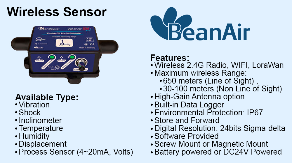
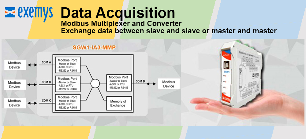
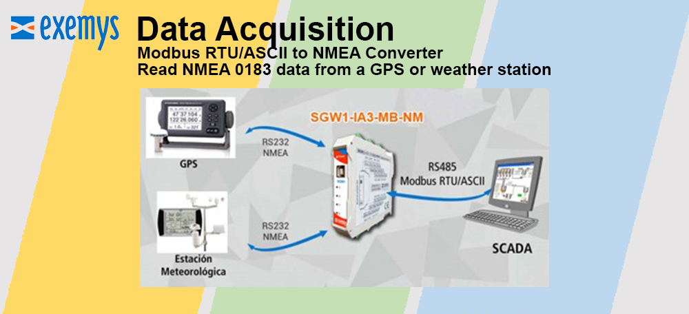
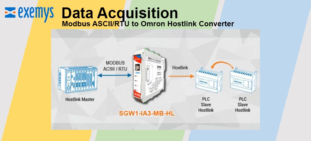
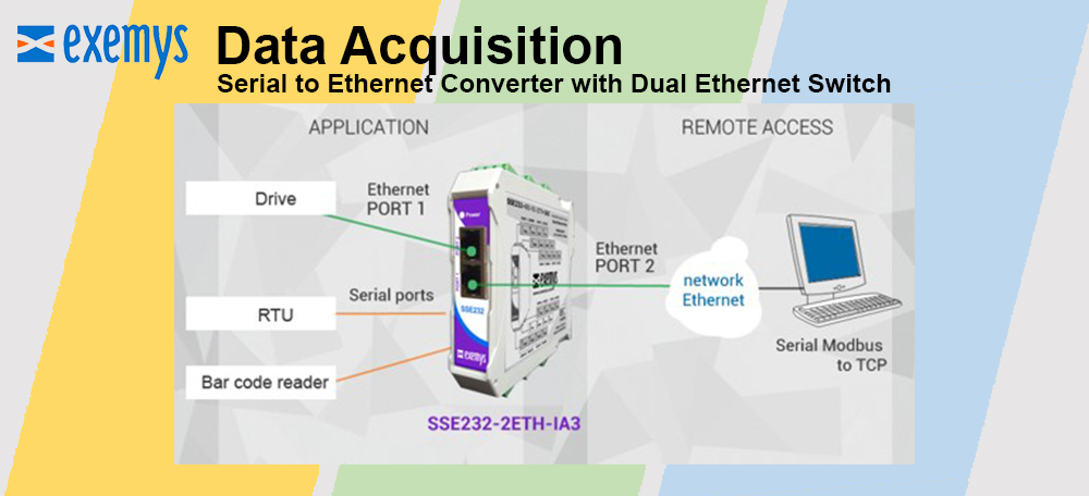
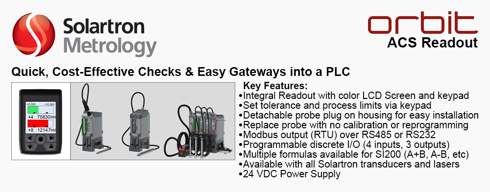
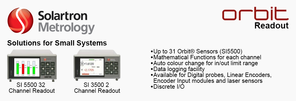
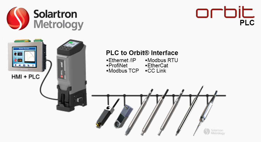
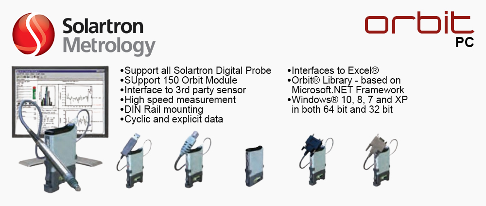
Standard product information
Repair Status
✔ (Maintenance service is available, able to be maintained.)
Display specifications
Effective display area
W115.2 x H86.4 mm [W4.54 x H3.40 in.]
Display colors
65,536 colors (No blink) / 16,384 colors (Blink)
Backlight
White LED (Not user replaceable. When replacement is required, contact your local distributor.)
Backlight service life
50,000 hrs. or more (each in continuous operation at 25 °C [77 °F] before backlight brightness decreases to 50%)
Brightness control
16 Levels (Adjusted with touch panel or software)
Language fonts
Japanese: 6,962 (JIS Standards 1 & 2) (including 607 non-kanji characters), ANK: 158 (Korean, Traditional Chinese, Simplified Chinese, Thai and Cyrillic can be added from the font setting of the screen editor. )
Character sizes
Standard font: 8 x 8, 8 x 16, 16 x 16 and 32 x 32 pixel fonts, Stroke font: 6 to 127 pixel fonts, Image font: 8 to 72 pixel fonts
Font sizes
Standard font: Width can be expanded up to 8 times. Height can be expanded up to 8 times.*1
Electrical specifications
Noise immunity
Noise Voltage : 1,000 Vp-p
Voltage endurance
1,000 Vac, 20 mA for 1 minute (between power terminal and FG terminals)
Insulation resistance
500 Vdc, 10 MΩ or more (between power terminal and FG terminals)
Environmental specifications
International safety standards
Surrounding air temperature
0 to 55 °C [32 to 131 °F]
Storage temperature
-20 to +60 °C [-4 to 140 °F]
Ambient humidity
10 to 90 % RH (Wet bulb temperature: 39 °C [102.2 °F] max. - no condensation)
Storage humidity
10 to 90 % RH (Wet bulb temperature: 39 °C [102.2 °F] max. - no condensation)
Dust
0.1 mg/m3 (10-7 oz/ft3 ) or less (non-conductive levels)
Pollution degree
For use in Pollution Degree 2 environment
Air pressure (altitude range)
800 to 1,114 hPa (2,000 m [6,561 ft.] above sea level or less)
Vibration resistance
IEC/EN 61131-2 compliant2
Concussion resistance
IEC/EN 61131-2 compliant 147 m/s2 , X, Y, Z directions for 3 times
Electrostatic discharge immunity
Contact Discharge Method: 6 kV (IEC/EN61000-4-2 Level 3)
Memory
Application memory
When using GP-Pro EX: Removable System: No
Backup memory
When using GP-Pro EX: Battery: Replaceable battery / Primary battery for clock data backup
Clock accuracy
±65 sec./month (deviation at room temperature and power is OFF)*2
Interface specifications
Serial (COM1)
Asynchronous Transmission: RS-232C, Data Length: 7 or 8 bits, Stop Bit: 1 or 2 bits, Parity: None, Even or Odd, Data Transmission Speed: 2,400 to 115,200 bps, Connector: D-Sub 9 (plug)
Serial (COM2)
Asynchronous Transmission: RS-422 / 485, Data Length: 7 or 8 bits, Stop Bit: 1 or 2 bits, Parity: None, Even or Odd, Data Transmission Speed: 2,400 to 115,200 bps, 187,500 bps (MPI), Connector: D-Sub 9 pin (plug)
USB (Type A)
Conforms to USB 2.0 (Type A) x 1
USB (mini-B)
Conforms to USB 2.0 (mini-B) x 1, Communication Distance: 5 m [16.4 ft] or less
Ethernet
IEEE802.3i / IEEE802.3u, 10BASE-T / 100BASE-TX, Connector: Modular jack (RJ-45) x 1
Structural specifications
Grounding
Functional grounding: Grounding resistance of 100 Ω, 2mm2 (AWG 14) or thicker wire, or your country's applicable standard. (Same for FG and SG terminals)
External dimensions
W155.6 x H123.4 x D59.7 mm [W6.13 x H4.86 x D2.35 in.]
Panel cut-out dimensions
Standard Mount: W118.8 x H90 mm [W4.68 x H3.54 in.]*4
Dimensions
External dimensions
Panel Type/Standard Mount
Installation with Installation Fasteners attached to the top and bottom surfaces of the GP unit
Installation with Installation Fasteners attached to the sides of the GP unit
Panel Type/Flat Mount
Installation with Installation Fasteners attached to the top and bottom surfaces of the GP unit
Installation with Installation Fasteners attached to the sides of the GP unit
Resin Boss Type/Standard Mount, Flat Mount
Installation with Installation Fasteners attached to the top and bottom surfaces of the GP unit
Installation with Installation Fasteners attached to the sides of the GP unit
Panel cut-out dimensions
Standard Mount (Panel Type/Resin Boss Type)
a)
Installation positions of stud bolts or positions of boss molds when attaching installation brackets at the top and bottom surfaces of the GP unit
b)
Installation positions of stud bolts or positions of boss molds when attaching installation brackets on either side of the GP unit
d)
4-M4 x 10L stud bolts (no foreign material present on the base due to sparking or similar phenomena) or boss molds
e)
Center of the display area
A
B
C
R
Panel Type *1
Resin Boss Type *2
118.8mm (+0.5, -0mm) (4.68in. [+0.02, -0in.])
90mm (+0.5, -0mm) (3.54in. [+0.02, -0in.])
1.6mm (0.06in.) to 3.2mm (0.13in.) (SPCC "JIS G3141" or SECC "JIS G3313") 1.5mm (0.06in.) to 6mm (0.24in.) (SUS304 "JIS G4304, JIS G4305")
2mm (0.08in.) or more
1mm (0.04in.) maximum
Note: If you are designing the panel with a material other than sheet metal, ensure that the material has sufficient strength.*1 Panel type: Weld the stud bolts to the panel, and then tighten the nuts to fasten the GP unit to the panel.*2 Resin boss type: Tighten the screws to attach the GP unit to the bosses of the resin boss-molded product.
Attaching Installation Brackets
Attaching Installation Brackets
X1
Y1
X2
Y2
43 (±0.15) [1.69, (±0.01)]
69.5 (±0.15) [2.74, (±0.01)]
85.6 (±0.15) [3.37, (±0.01)]
43 (±0.15) [1.69, (±0.01)]
Note: Note that the panel cut dimensions have been calculated with the display area, not the panel cut (A or B), as the reference.
Flat Mount (Panel Type/Resin Boss Type)
a)
Installation positions of stud bolts or positions of boss molds when attaching installation brackets at the top and bottom surfaces of the GP unit
b)
Installation positions of stud bolts or positions of boss molds when attaching installation brackets on either side of the GP unit
d)
4-M4 x 10L stud bolts (no foreign material present on the base due to sparking or similar phenomena) or boss molds
e)
Center of the display area
A
B
C
R
A1
A2
Panel Type *1
Resin Boss Type *2
143mm (+0.5, -0mm) (5.63in.[+0.02, -0in.])
109mm (+0.5, -0mm) (4.29in. [+0.02, -0in.])
1.6 mm (0.06in.) (SPCC "JIS G3141" or SECC "JIS G3313") 1.5 mm (0.06in.) (SUS304 "JIS G4304, JIS G4305")
2 mm (0.08in.) maximum
1 mm (0.04in.) maximum
70.5mm (+0.25, -0mm) (2.78in. [+0.01, -0in.])
72.5mm (+0.25, -0mm) (2.85in. [+0.01, -0in.])
Note: If you are designing the panel with a material other than sheet metal, ensure that the material has sufficient strength.*1 Panel type: Weld the stud bolts to the panel, and then tighten the nuts to fasten the GP unit to the panel.*2 Resin boss type: Tighten the screws to attach the GP unit to the bosses of the resin boss-molded product.
Attaching Installation Brackets
Attaching Installation Brackets
X1
Y1
X2
Y2
43 (±0.15) [1.69, (±0.01)]
69.5 (±0.15) [2.74, (±0.01)]
85.6 (±0.15) [3.37, (±0.01)]
43 (±0.15) [1.69, (±0.01)]
Note: Note that the panel cut dimensions have been calculated with the display area, not the panel cut (A or B), as the reference.
External dimensions with cable
Panel Type (Standard, Flat Mount) / Resin Boss Type (Standard Mount)
NOTE : All the above values are designed with cable bending in mind. The dimensions given here are representative values depending on the type of connection cable in use. Therefore, these values are intended for reference only.