|
|
PFXSTC6300TADDKE / PFXSTC6300TADDCE
|
|
Display Specifications |
|
Model No. |
PFXSTC6300TADDKE |
PFXSTC6300TADDCE |
|
Display Type |
TFT Color LCD |
|
Display Size |
5.7" |
|
Resolution |
640 x 480 pixels |
|
Effective Display Area |
115.2 x 86.4 mm (4.54 x 3.40 in) |
|
Display Colors |
262,144 colors
For details about display colors, refer to the manual of your screen editing software. |
|
Backlight |
White LED (White LED (Not replaceable. Please contact customer support.)) |
|
Backlight Service Life |
50,000 hours or more (continuous operation at 25 °C [77 °F] before backlight brightness decreases to 25%) |
|
Brightness Control |
16 levels (Adjusted with touch panel or software) |
|
Touch Panel Type |
Resistive film (analog, single touch) |
|
Touch Panel Resolution |
1,024 x 1,024 |
|
Touch Panel lifetime |
1,000,000 times or more |
|
|
|
|
Electrical Specifications |
|
Model No. |
PFXSTC6300TADDKE |
PFXSTC6300TADDCE |
|
Rated Input Voltage |
24 Vdc |
|
Input Voltage Limits |
19.2 to 28.8 Vdc |
|
Voltage Drop |
5 ms or less |
|
Power Consumption |
Max |
11.3 W |
|
When power is not supplied to external devices |
8 W or less |
When screen turns off the backlight
(Standby Mode) |
5.6 W or less |
|
In-Rush Current |
30 A or less |
|
Noise immunity |
Noise voltage: 1,000 Vp-p, pulse duration: 1 μs, rise time: 1 ns (via noise simulator) |
|
Voltage Endurance |
1,000 Vac, 20 mA for 1 minute (between charging and FG terminals) |
|
Insulation Resistance |
500 Vdc, 10 MΩ or more |
|
|
|
|
Environmental Specification |
|
Model No. |
PFXSTC6300TADDKE |
PFXSTC6300TADDCE |
|
Certification |
CE, UL and cUL, UKCA, RCM, KC, ATEX, RoHS, WEEE |
|
Ambient air temperature |
0 to 50 °C (32 to 122 °F) |
|
Storage Temperature |
-20 to 60 °C (-4 to 140 °F) |
|
Ambient air and storage humidity |
10%...90% RH (Non condensing, wet bulb temperature 39 °C [102.2 °F] or less) |
|
Dust |
0.1 mg/m3 (10-7 oz/ft3) or less (non-conductive levels) |
|
Pollution Degree |
For use in Pollution Degree 2 environment |
|
Corrosive Gases |
Free of corrosive gases |
|
Air pressure (altitude range) |
800 to 1,114 hPa (2,000 m [6,561 ft.] above sea level or less) |
|
Vibration Resistance |
IEC/EN 61131-2 compliant
5 to 9 Hz single amplitude 3.5 mm [0.14 in.]
9 to 150 Hz fixed acceleration: 9.8 m/s2
X, Y, Z directions for 10 cycles (approx. 100 min.) |
|
Shock Resistance |
IEC/EN 61131-2 compliant 147 m/s2, X, Y, Z directions for 3 times |
|
Electrical fasttransient/burst |
IEC 61000-4-4
2 kV: Power port (display unit)
1 kV: Signal ports |
|
Electrostatic Discharge Immunity |
Contact Discharge Method: 6 kV
Air Discharge Method: 8 kV
(IEC/EN61000-4-2 Level 3) |
|
|
|
|
Structural Specification |
|
Model No. |
PFXSTC6300TADDKE |
PFXSTC6300TADDCE |
|
Grounding |
Functional grounding: Grounding resistance of 100 Ω, 2 mm2 (AWG 14) or thicker wire, or your country’s applicable standard. |
|
Cooling Method |
Natural air circulation |
|
Structure*1 |
IP65F, UL 50/50E, Type 1, Type 4X (indoor use only), Type 13 (on the front panel when properly installed in an enclosure) |
|
External Dimensions |
169.5 x 137 x 60 mm
(6.67 x 5.39 x 2.36 in) |
|
Panel Cut Dimensions |
156 x 123.5 mm
(6.14 x 4.86 in)
Panel thickness area:1.6...5 mm (0.06...0.2 in)*2 |
|
Weight |
0.8 kg (1.76 lb) or less |
|
|
|
|
Interface Specification |
|
Model No. |
PFXSTC6300TADDKE |
PFXSTC6300TADDCE |
|
Serial (COM1) |
Asynchronous Transmission: RS-232C/422/485,
Data Length: 7 or 8 bits,
Stop Bit: 1 or 2 bits,
Parity: None, Even or Odd,
Data Transmission Speed: 2,400 to 115,200 bps,
Connector: D-Sub 9 (plug) |
|
USB(Type A) |
Conforms to USB 2.0 (Type A) x 1
Power supply voltage: 5 Vdc ±5 %
Output Current: 500 mA/port
Maximum transmission distance : 5 m [16.4 ft.] |
|
USB (micro-B) |
Conforms to USB 2.0 (micro-B) x 1,
Maximum transmission distance : 5 m [16.4 ft] |
|
Ethernet |
IEEE802.3i/IEEE802.3u, 10BASE-T/100BASE-TX,
Connector: Modular jack (RJ-45) x 1 |
|
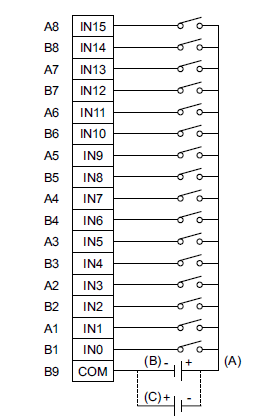
DIO
|
DIO Connector: 38 pin connector (Model number: CA7-DIOCN5-01)
Cable connection side: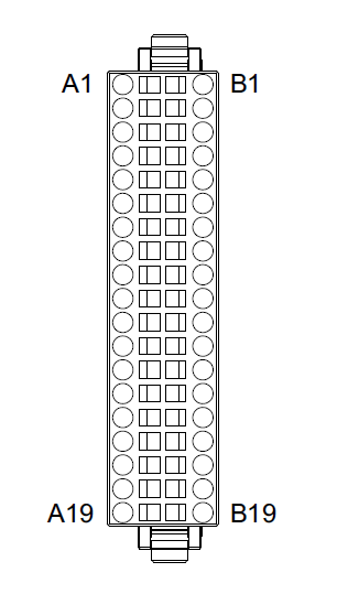
|
Pin No. |
Signal name |
Pin No. |
Signal name |
|
A1 |
IN1 |
B1 |
IN0 (CT0)*3 |
|
A2 |
IN3 |
B2 |
IN2 (CT1)*3 |
|
A3 |
IN5 |
B3 |
IN4 (CT2)*3 |
|
A4 |
IN7 |
B4 |
IN6 (CT3)*3 |
|
A5 |
IN9 |
B5 |
IN8 |
|
A6 |
IN11 |
B6 |
IN10 |
|
A7 |
IN13 |
B7 |
IN12 |
|
A8 |
IN15 |
B8 |
IN14 |
|
A9 |
NC |
B9 |
COM |
|
A10 |
Sink: NC |
B10 |
Sink: +24 Vdc |
|
Source: +24 Vdc |
Source: +24 Vdc |
|
A11 |
Sink: 0 Vdc |
B11 |
Sink: 0 Vdc |
|
Source: NC |
Source: 0 Vdc |
|
A12 |
OUT1 (PLS1, PWM1)*4 |
B12 |
OUT0 (PLS0, PWM0)*4 |
|
A13 |
OUT3 (PLS3, PWM3)*4 |
B13 |
OUT2 (PLS2, PWM2)*4 |
|
A14 |
OUT5 |
B14 |
OUT4 |
|
A15 |
OUT7 |
B15 |
OUT6 |
|
A16 |
OUT9 |
B16 |
OUT8 |
|
A17 |
OUT11 |
B17 |
OUT10 |
|
A18 |
OUT13 |
B18 |
OUT12 |
|
OUT15 |
B19 |
OUT14 |
|
|
|
|
|
|
|
|
|
Digital Output Specifications |
|
Model No. |
PFXSTC6300TADDKE |
PFXSTC6300TADDCE |
|
Input terminal |
OUT0...OUT3 |
OUT4...OUT15 |
|
Rated voltage |
24 Vdc |
|
Rated voltage range |
20.4 Vdc...28.8 Vdc |
|
Output type |
PFXSTC6300TADDKE: Sink output |
|
PFXSTC6300TADDCE: Source output |
|
Maximum load current |
0.3 A/point, total 3.2 A |
|
Minimum load current |
1 mA |
1 mA |
|
(Pulse/PWM output unavailable) |
|
Output voltage drop |
1.5 Vdc or less |
|
Output delay time |
OFF to ON (With output at 24 Vdc, 200 mA) |
5 μs or less |
50 μs or less |
|
ON to OFF (With output at 24 Vdc, 200 mA) |
5 μs or less |
50 μs or less |
|
Type of output |
Transistor output |
|
Common lines |
2 |
|
Common design |
8-point/1 common line x 2 |
|
External connection |
38 pin connector (used with Input section) |
|
Output protection type |
Output is unprotected |
|
Output points |
16 |
|
Output signal display |
No LED indicators |
|
Status display |
None |
|
Isolation |
Yes |
|
External power supply |
For Signal: 24 Vdc |
|
Cable length |
Normal input |
Maximum 150 m (492 ft) |
|
Pulse/PWM output |
Maximum 5 m (16 ft) |
Output Circuit: Sink type
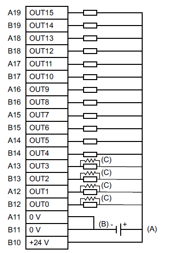
A. 24 Vdc External power supply
B. Sink type
C. Dummy resistor*5
Output Circuit: Source type

A. 24 Vdc External power supply
B. Source type
C. Dummy resistor *5
|
|
|
|
High-Speed Counter |
|
Model No. |
PFXSTC6300TADDKE |
PFXSTC6300TADDCE |
|
Input |
24 Vdc open collector |
24 Vdc open collector |
|
Input points |
CT0 (IN0), CT1 (IN2), CT2 (IN4), CT3 (IN6) |
CT0 (IN0), CT1 (IN2) (used as pair)
CT0: A Phase, CT1: B Phase
CT2 (IN4), CT3 (IN6) (used as pair)
CT2: A Phase, CT3: B Phase |
Minimum pulse width
(Pulse Input) |
 |
Count speed
(Rise, Fall time) |

t = 1 μs or less (100 kpps) |
|
Phase |
1 phase |
90 degree phase differential |
|
2 phase signal |
|
1 phase+ directional signal |
|
High speed count frequency |
100 kpps |
50 kpps |
|
Count edge designation |
Available |
Not available |
|
Count register |
32 bit UP/DOWN counter |
|
Counter mode change |
Set through software |
|
Upper/Lower limit setting |
Not available |
|
Preload - Prestrobe |
Available |
|
Marker Input (Counter value clear) |
None |
IN3, IN7 |
|
|
|
|
Pulse Catch Input |
|
Model No. |
PFXSTC6300TADDKE |
PFXSTC6300TADDCE |
|
Input |
24 Vdc open collector |
|
Input points |
IN0, IN2, IN4, IN6 |
Minimum pulse width
(Pulse Input) |
Input signal ON width
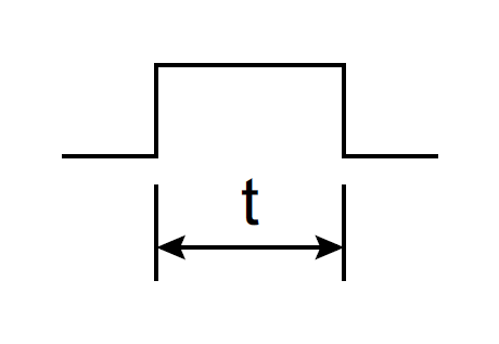
t = 5 μs or more |
|
|
|
|
Pulse Output |
|
Model No. |
PFXSTC6300TADDKE |
PFXSTC6300TADDCE |
|
Output points |
4 |
|
Output method |
PLS0...PLS3 (OUT0...OUT3)*6 |
|
Load voltage |
24 Vdc |
|
Maximum load current |
50 mA/1-point |
|
Minimum load current |
1 mA |
|
Maximum output frequency |
Up to 65 kHz/1-point*6 |
|
Pulse acceleration / Deceleration speed |
Available |
|
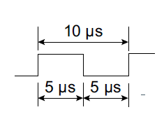
ON duty |
50% ±10% (at 65 kHz)*7 |
|
|
|
|
PWM Output |
|
Model No. |
PFXSTC6300TADDKE |
PFXSTC6300TADDCE |
|
Output points |
4 |
|
Output method |
PWM0...PWM3 (OUT0...OUT3)*8 |
|
Load voltage |
24 Vdc |
|
Maximum load current |
50 mA/1-point |
|
Minimum load current |
1 mA |
|
Maximum output frequency |
Up to 65 kHz/1-point*8 |
|
ON duty |
19...81% (at 65 kHz)*9 |
|
|
|
|
Memory |
|
Model No. |
PFXSTC6300TADDKE |
PFXSTC6300TADDCE |
|
Application memory |
Editor : GP-Pro EX |
Media |
FLASH EPROM |
|
Screen area*10 |
64 MB |
|
User font area |
8 MB |
|
Logic program area |
132KB(Equivalent to 15,000 steps) |
|
Free space |
ー |
|
Removable system |
No |
|
Backup memory |
Editor : GP-Pro EX |
Screen area |
SRAM 320 KB |
|
Variable area |
SRAM 64 KB |
|
Battery |
Replaceable battery / Primary battery for clock data backup |
|
|
|
|
Panel Cut Dimensions |
Based on the panel cut dimensions, open a mount hole on the panel.
 |
|
A |
B |
C |
156 mm (+1/-0 mm)
(6.14 in [+0.04/-0 in]) |
123.5 mm (+1/-0 mm)
(4.86 in [+0.04/-0 in]) |
1.6...5 mm
(0.06...0.2 in) |
|
|
|
|
External Dimensions / Parts Identification |
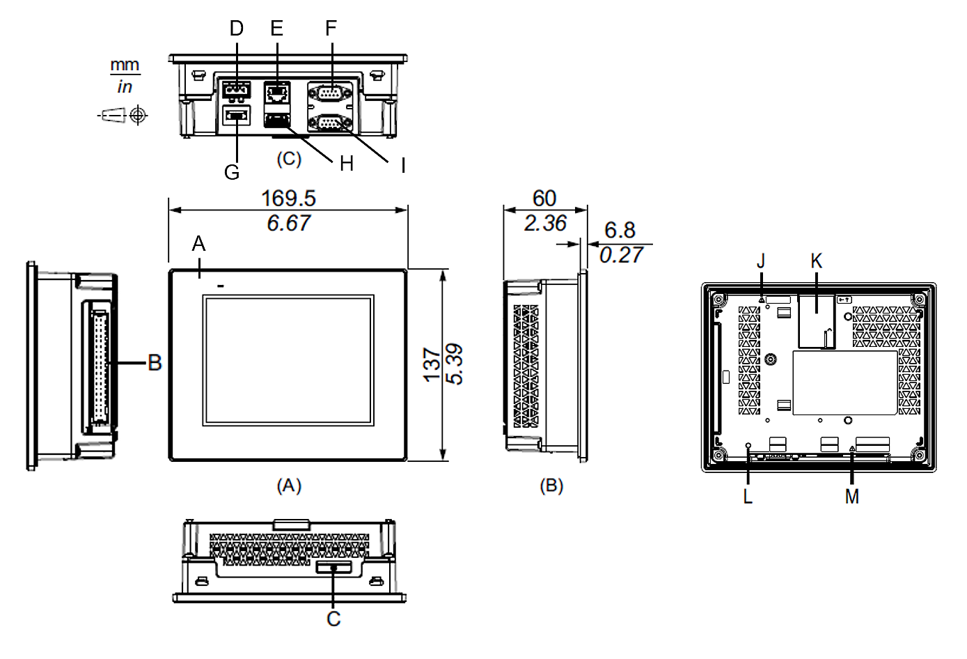 |
-
Status LED
-
DIO interface
-
Battery slot
-
Power plug connector
-
Ethernet interface (ETH)
-
CANopen interface (CAN)
-
USB (micro-B) interface
-
USB (Type A) interface
-
Serial interface (RS-232C/422/485) (COM)
-
Safety alert symbol
-
Expansion module interface
-
CANopen LED
-
Safety alert symbol
|
|
|
|
|
|
|
|