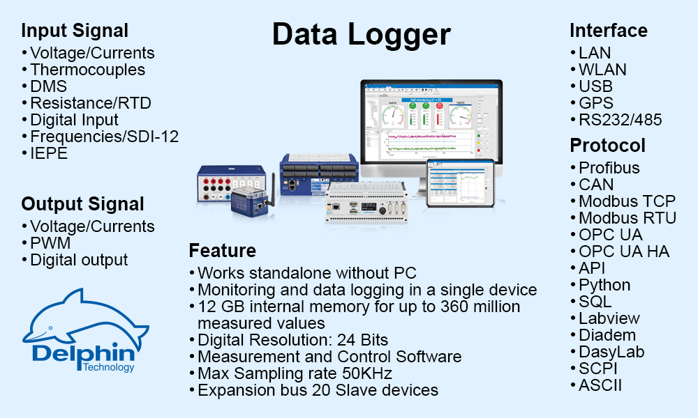

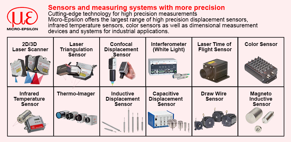


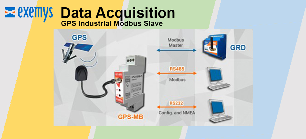


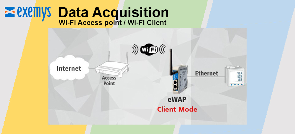

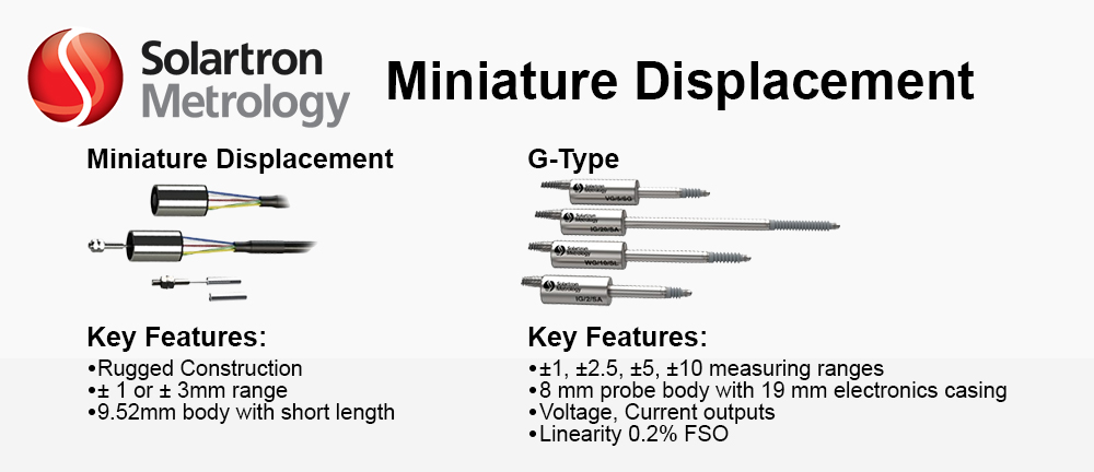


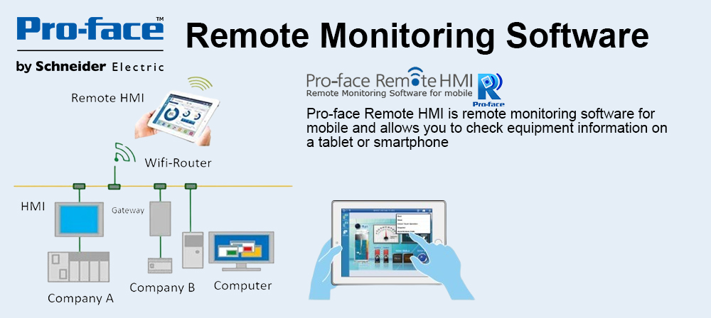


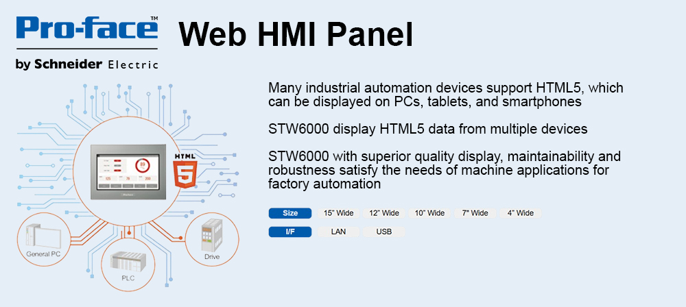
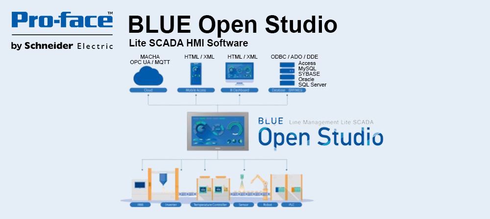


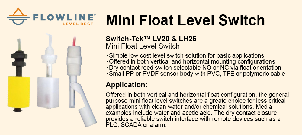
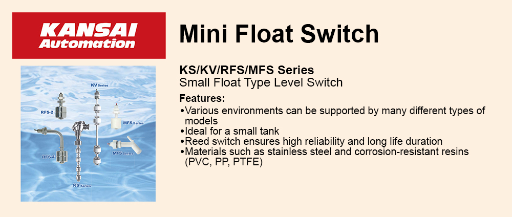
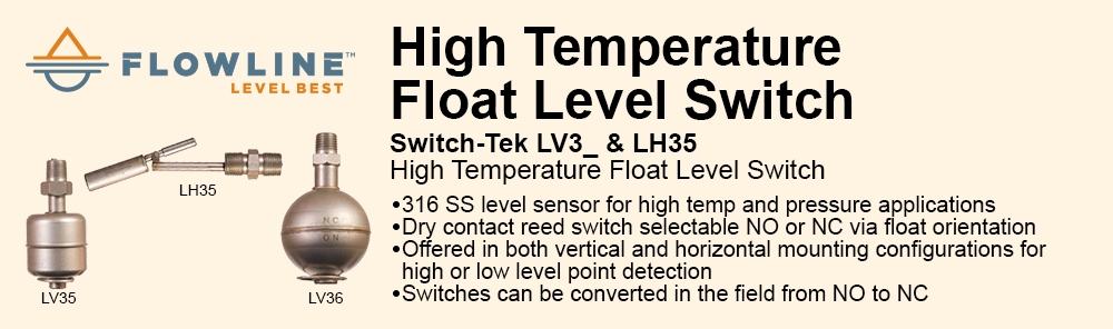
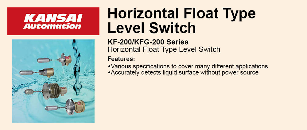
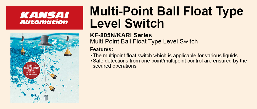
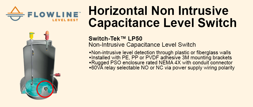
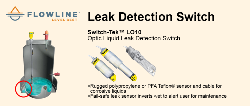
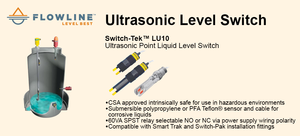
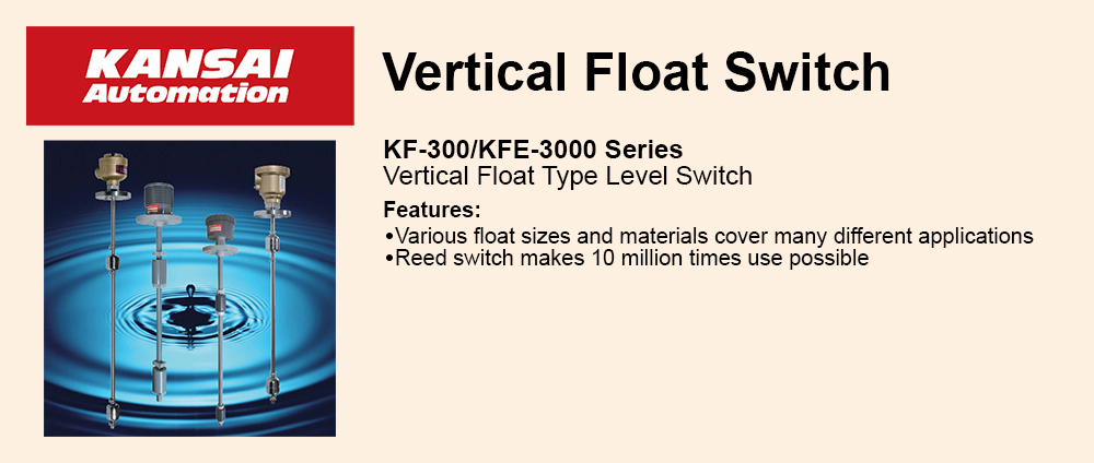

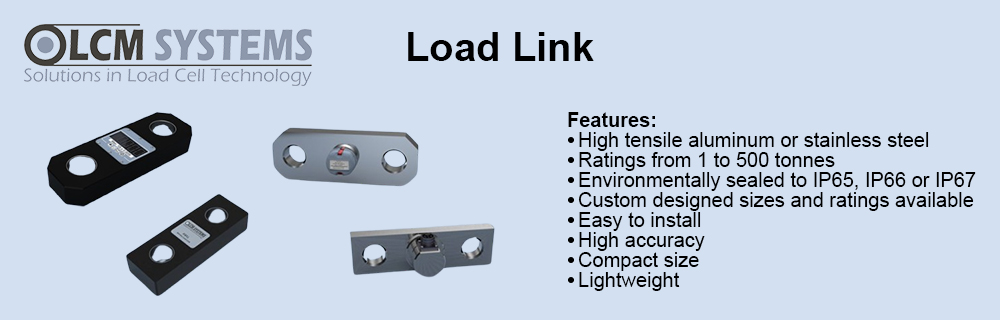


Paper and printing technology |
 An important requirement is that the production in paper and printing technology runs without errors. Small deviations from the specified dimensions quickly become apparent during the fast running processes. Precise displacement sensors from Micro-Epsilon avoid such types of situations. Temperature monitoring in this sector is a safety function. Preventive action in systems and machines can be taken before dangerous situations occur. |
Web-edge detection in the calender of a paper machine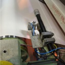 If movement of the paper web in the calender is not exactly executed in one line, the heated calender roller is pressed directly onto the coating of the opposite roller, which can damage it. Repairing this special coating or even replacing the whole roller would be very costly, which is why it is mandatory to control the position of the web edge. This is where laser line sensors from Micro-Epsilon are utilized, transferring the exact position of the web edge directly to the machine control system. Sensor technology applied |
| __________________________________________________________________________________________________________ |
Print head positioning using laser triangulation sensors When printing on materials such as glass and ceramics, very fine detailed structures are generated, which requires precise positioning of the print head. This is why optoNCDT 1420 laser triangulation sensors from Micro-Epsilon are used. With a measuring range of 10mm, these determine at various points in the print head the respective distance from the surface to be printed. The sensor data is transferred via the RS422 interface to the control system. The data obtained enables the determination of the edges and the surface tilt and therefore the exact positioning of the print head. Sensor technology applied |
| __________________________________________________________________________________________________________ |
Rebound behavior of the feltIn paper production the paper band is transported over a felt conveyer from the screen station to the pressing station. This felt removes the residual moisture from the paper. For water separation the felt passes a defined gap between the central and the suction roller. The wear and the rebound behavior of the felt determine the hygroscopy and are thus of decisive importance for the paper quality. Laser-optical position measuring systems monitor the wear at a guide roller. Measuring with two sensors compensates the ovality / stroke of the guide roller. The result of the measurement is the effective thickness of the felt. If the measured value falls below the specified limits of wear, the production can be stopped and the felt can be replaced. Because of the difficult environmental conditions the sensors are installed in a protective housing. Sensor technology applied |
| __________________________________________________________________________________________________________ |
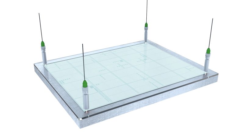
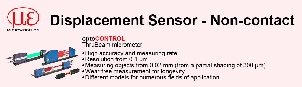
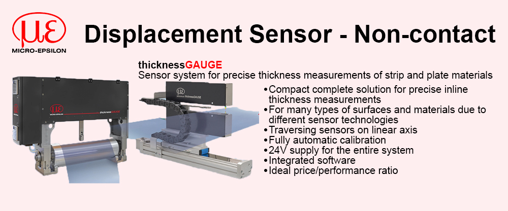
Thickness measurement using displacement sensors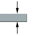 Thickness measurement using displacement sensors is a wide application area. Basically there are distinctions between non-destructive/destructive, non-contact/with contact and one-side/two-sided thickness measurement. The Micro-Epsilon measuring techniques for thickness measurement are all emission-free whereby no emissions regulations of any kind have to be complied with. Thickness measurements must be performed both with contacting as well as with non-contact sensors whereby non-contact measuring techniques show advantages as regards accuracy and measuring speed. There is also a distinction between one-sided and two-sided thickness measurement. Two-sided thickness measurements are carried out with at least one pair of sensors which are installed together on one axis. This pair of sensors measures the target synchronously. The difference between the measurement results (C-A-B) produces the thickness of the measuring object. One-sided thickness measurements must only be performed with non-contact sensors. In doing so, the target is only measured with one sensor and either only a part of the target thickness (e.g. layer thickness) or the complete measuring object thickness is measured. Thickness measurements are mainly used in process control and quality assurance, e.g. for the control of extrusion systems or 100% checking of tube diameters. Sensor technology applied |
| __________________________________________________________________________________________________________ |
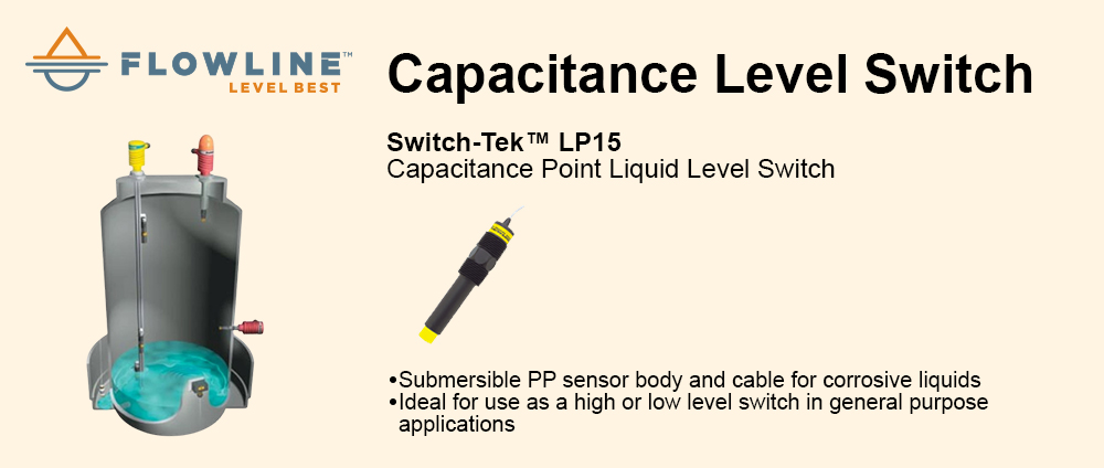
Automatic paper roll control In paper production the prepared paper pulp flows onto a conveyor belt of fine wire mesh at the so called "wet end". There most of the water is removed by means of a vacuum. The paper web is generated and is transported to the second station, the wet press rollers, which determine the paper web speed by means of a second drive unit. In order to avoid tears in the paper web a laser position measuring system is used here which measures the position of the paper web between the two stations. The analog output signal of the sensor is fed into a closed-loop control circuit which influences the motor speed at station 1 and thereby ensures that a specified setpoint distance value is maintained. Sensor technology applied |
| __________________________________________________________________________________________________________ |
Paper fold recognition in printing machines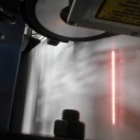 Possible folds produced in the paper web that remain unnoticed can have far-reaching consequences during processing and often lead to unusable printed products. Extreme differences in printing registration, i.e. inaccuracies when correlating overlapping colors may also occur. Another risk is that the paper web tears while going through the print machine. Any machine stoppages or changeovers can significantly increase printing costs. Non-contact, optical measurement technology is a suitable solution. Sensor technology applied |
| __________________________________________________________________________________________________________ |
Lip Gap Measuring in Paper Manufacture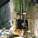 In paper manufacture the lip gap at the headbox determines the thickness of the paper. Paper machines usually have a lip width between 4 and 6 metres. The measuring task is a constantly monitoring the gap between the upper and lower lip as a quality relevant variable. To manage this application a non-contact eddy current displacement sensor is fitted either to one or better to both sides. A steel or aluminum target plate fitted opposite the sensor serves as a measuring target. Sensor technology applied |
| __________________________________________________________________________________________________________ |
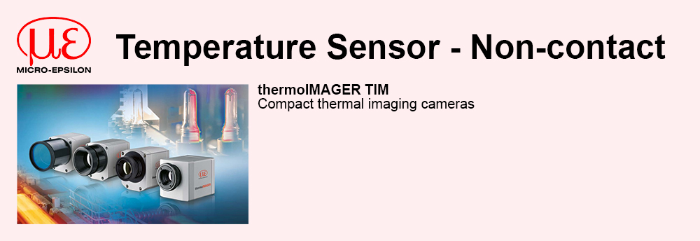
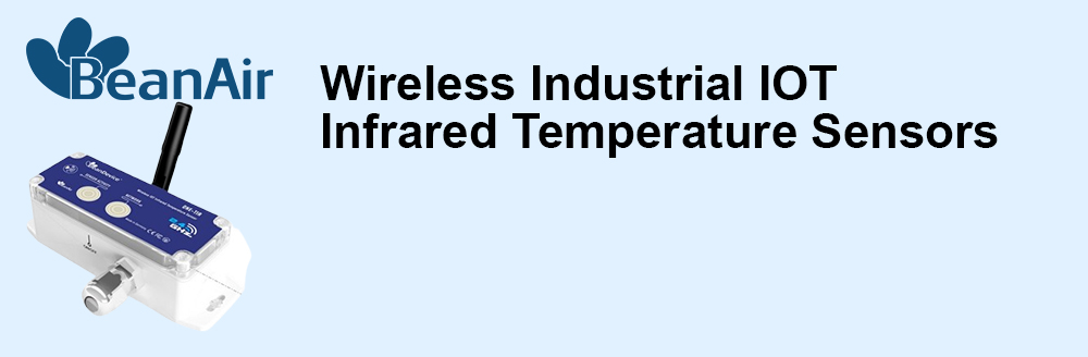
Paper, packaging industry - temperature measurement Non-contact IR thermometers from Micro-Epsilon are used for fast and non-contact temperature measurement for the manufacture of paper products, particularly in the areas of coating and drying. Sensor technology applied |
| __________________________________________________________________________________________________________ |
Layer thickness measurement (non contacting)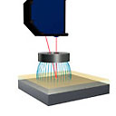 Layer thickness measurement belongs to the group of one-sided, non-contact thickness measurement. Basically, only the layer thickness of electrical insulators can be measured for opaque objects. An eddy current sensor penetrates the insulating layer without damage and measures the distance to a layer underneath it. At the same time, a second sensor, a laser triangulator measures the insulating layer. The layer thickness is obtained by offsetting both signals. This method of measuring with two sensors using different principles is called the dual sensor technique by Micro-Epsilon. A second possibility is the layer thickness measurement of transparent materials using confocal measurement technology. The emitted white light penetrates the measuring object and provides a peak in the signal graph at every material transition. For example, the film thickness between two glass panes can be easily measured in this way. Sensor technology applied |
| __________________________________________________________________________________________________________ |
Measurement system for cut packaging pieces Manufacturers in the packaging industry make high demands with regard to their production quality. For sampling inspection for example, the cut pieces of packaging are extracted from the production, placed in a measurement system and a nozzle system draws them down flat by suction. A non-contacting triangulation sensor scans the surface to measure the topography of the cardboard and to determine the line of the grooves, edges and the associated lengths to high accuracy. Sensor technology applied |
| __________________________________________________________________________________________________________ |
Roller levitation height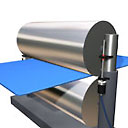 The distance of both rollers from each other or from the roller to the support surface is the crucial dimension for rolling processes for metals, plastics or other materials. In the case of sensitive processes and high material accuracies, the lift of the upper roller must be checked constantly so that imminent rejection is avoided. The contacting inductive and the non-contact methods are suitable for this. In the case of contacting methods, the sensor is mounted on the outside on the roller guide. The change in clearance is transmitted to a plunger whose position change is measured by the inductive sensor. In the case of the non-contact method, the roller is between the transmitter and receiver of an optical micrometer at the height of the lift. The emitted light curtain is partially covered by the roller. The remainder reaches the receiver through the gap. The gap can be calculated based on the light quantity measurement. Sensor technology applied |
| __________________________________________________________________________________________________________ |
Roller runout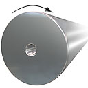 The runout of the roller is a crucial criterion for rolling processes of metals, plastics or other materials. An imbalance is even dangerous for rollers which have to rotate at high speeds. Therefore, the roundness of the roller must be measured before and also during the application. For all the following processes, a sensor measures the roller directly and establishes the ovality. The non-contact eddy current method is used for rollers made of polished metal. Capacitive or laser triangulation sensors are used for rollers made of other materials. Sensor technology applied |
| __________________________________________________________________________________________________________ |
Roller clearance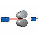 The distance of both rollers from each other or from the roller to the support surface is the crucial dimension for rolling processes for metals, plastics or other materials. In the case of sensitive processes and high material accuracies, the clearance must be checked constantly so that imminent rejection is avoided. The contacting inductive and the non-contact methods are suitable for this. In the case of contacting methods, the sensor is mounted on the outside on the roller guide. The change in clearance is transmitted to a plunger whose position change is measured by the inductive sensor. In the case of the non-contact method, the roller is between the transmitter and receiver of an optical micrometer. The emitted light curtain is partially covered by the roller. The remainder reaches the receiver through the gap. The gap can be calculated based on the light quantity measurement. Sensor technology applied |