|
|
 |
|
|
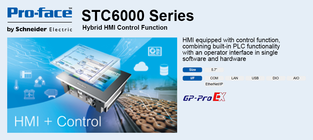
5.7-inch Controller
Input Specifications
|
Rated Voltage |
DC24V |
|
Maximum Allowable Voltage |
DC28.8V |
|
Input Method |
Sink/ Source Input |
|
Rated Current |
6.5mA (DC24V) (IN0, IN2, IN4, IN6)
4.1mA (DC24V) (Other inputs) |
|
Input Resistance |
Approx. 3.7kΩ (IN0, IN2, IN4, IN6)
Approx. 5.9kΩ (Other inputs) |
|
Input Points |
16 points |
|
Common Lines |
1 |
|
Common Design |
16 points/ 1 common line |
|
Operation Range |
ON Voltage |
DC19V or more |
|
OFF Voltage |
DC5V or less |
|
Input Delay Time |
OFF→ON |
0.5 to 20ms *1 |
|
ON→OFF |
0.5 to 20ms *1 |
|
Input Signal Display |
No LED indicators |
|
Insulation Method |
Photocoupler isolation |
|
External Connection |
38-pin connector (used with Output section) |
|
External Power Supply |
For Signal: DC24V |
Output Specifications
|
|
OUT0 to OUT3 |
OUT4 to OUT15 |
|
Rated Voltage |
DC24V |
|
Allowance Voltage Range |
DC20.4V to DC28.8V |
|
Output Method |
Sink Output |
LT3300-S1-D24-K, LT3300-L1-D24-K, LT3301-L1-D24-K |
|
Source Output |
LT3300-S1-D24-C, LT3300-L1-D24-C, LT3301-L1-D24-C |
|
Maximum Load Voltage |
200mA/1point, 1.6A/1 common |
|
Minimum Load Current |
1mA |
1mA
(Pulse/ PWM Output Unavailable) |
|
Output Voltage Drop |
DC0.5V or les |
|
Output Delay Time |
OFF→ON |
5µs or less
(at Output DC24V, 200mA) |
0.5m or less
(at Output DC24V, 200mA) |
|
ON→OFF |
5µs or less
(at Output DC24V, 200mA) |
0.5ms or less
(at Output DC24V, 200mA) |
|
Voltage Leakage (When OFF) |
0.1mA or less |
|
Clamp Voltage |
39V ±1V |
|
Type of Output |
Transistor Output |
|
Common Lines |
2 |
|
Common Design |
8 points/ 1 common line × 2 |
|
External connection |
38-pin connector (also used for Input) |
|
Output Protection Type |
Output is unprotected |
|
Internal Fuse |
2.5A, 125V Chip fuse × 2 (not replaceable) |
|
Surge Control Circuit |
Zener diode |
|
Output points*1 |
16 points |
|
Input Signal Display |
No LED indicators |
|
Isolation Method |
Photocoupler Isolation |
|
External Power Supply |
For Signal: DC24V |
High-speed Counter/ Pulse Catch Input Specifications
|
|
High-speed Counter |
Pulse Catch Input |
|
Input *1 |
DC24V Open collector |
DC24V
Open collector |
|
Single phase (4 points) |
Double phase
(1 point or 2 points) |
|
Input Points |
CT0(IN0),
CT1(IN2),
CT2(IN4),
CT3(IN6)
defined by user |
CT0(IN0), CT1(IN2) (used as pair)
CT0: A phase, CT1: B phase
CT2 (IN4), CT3 (IN6)
CT3: Phase A, CT3: Phase B
defined by user |
IN0, IN2, IN4, IN6
defined by user |
Minimum Pulse Width
(Pulse Input) |
|
|
|
Count Speed
(Rise, Fall Time)
|
|
-
|
|
Phase |
1 phase |
90 degree-phase differentional 2-phase signal / 1-phase + directional signal |
-
|
|
High Speed Count Frequency |
100Kpps |
50Kpps |
-
|
|
Count Edge Designation |
Available |
Not available |
-
|
|
Count Register |
32-bit UP/ DOWN counter |
-
|
|
Counter Mode Charge |
Set through software |
-
|
|
Upper/ Lower Limit Settings |
Not available |
-
|
|
Preload/Prestrobe |
Available |
-
|
Marker Input
(Clear Counter Value) |
None |
IN3, IN7 |
-
|
Pulse/ PWM Output Specifications
|
|
Pulse output |
PWM output |
|
Output Points*1 |
4 points |
|
Output Method |
PLS0 to PLS3
(OUT0 to OUT3)
defined by user |
PWM0 to PWM3
(OUT0 to OUT3)
defined by user |
|
Load Voltage |
DC24V |
|
Minimum Load Current |
1mA |
|
Maximum Output Frequency |
Up to 65kHz possible per point (set through software)
Varies depending on the number of CH of High-speed counter, pulse output. |
|
Pulse Acceleration Deceleration Speed |
Available |
Not available |
|
ON Duty |
50% ± 10% (at 65kHz)*2 |
19 to 81% (at 65kHz)*3 |
-
*1 Digital filter can be set intervals of 0.5ms.
-
*2 The ON Duty error (10%) will be reduced if the Output frequency is low.
-
*3 ON duty (effective range) increases as the output frequency setting is lower.
|
|
|
|
|
|
|