Metrology Glossary of Terms
A
Accuracy
The accuracy of all solartron Metrology Digital Sensors is quoted as % of reading, which is the method that is least open to interpretation (as opposed, for example, to best fit).
______________________________________________________________________________________________________
D
Direction of Displacement Measurement
Outward travel is defined as displacement away from the body of the transducer and cable end. Inward travel is defined as displacement into the body of the of the transducer towards the cable end. The conventional direction of signals for an LVDT is such that an inward displacement from the electrical null the output signal is in phase with the excitation signal and for an outward displacement from electrical zero the output signal is in antiphase to the excitation signal. For a digital transducer the output count increases for inward movement.
Pulse sent from the Dynamic capable controllers which tells the Orbit® Modules to take a reading. This pulse is either generated by an Orbit® 3 controller or by another Orbit® Module that is given authority to generate the synchronisation pulses by the controller. This is particularly useful when using the Encoder Input Modules, allowing synchronized measurements between angular and linear measurement, e.g. Profiling.
______________________________________________________________________________________________________
E
Electrical Zero
The position of the moving part of the transducer with respect to its body where the electrical output is zero. In practice, this is the transducer position where the output is minimised.
Note: Sometimes known as 'Null'.
Energising Voltage
The allowable voltages used to energise the LVDT or Half Bridge. It is specified as a sine wave in Vrms. The energising voltage is the range over which the transducer will operate, however the transducer specification is guaranteed only at the calibration energising voltage. For DC operated transducers, the energising voltage is specified in VDC.
Energising Current
The current required to energise the transducer. It is dependent on the energising voltage and is expressed as mA/V. It also varies with the energising frequency.
Energising Frequency
The allowable range of frequencies used to energise an LVDT or Half-bridge transducer, It is specified in kHz. The result. The energising frequency is the range over which the transducer will operate, however the transducer specification is guaranteed only at the calibration energising frequency.
______________________________________________________________________________________________________
H
Hysteresis
Hysteresis is defined as the difference between measurements on the same measured from opposite directions.
______________________________________________________________________________________________________
I
This is the total mechanical movement inward from the electrical zero of an LVDT or HB Transducer. It is generally greater than the measurement range from the electrical zero (see also Pre-Travel).
______________________________________________________________________________________________________
L
Linearity
Linearity is defined as the deviation of a transducer's response from a straight line.
Solartron uses two definitions for linearity depending on the product type. These are % FRO and the more demanding, % of Reading (0.5% reading approximately equals 0.25% FRO).
% Full Range Output (FRO) fits a straight line through zero to the measured characteristic which balances the positive and negative errors from this line. This is known as the "Best Fit Line". The magnitude of this error is then expressed as a % of full range and includes any error due to symmetry either side of zero but does not include any sensitivity error.
% Reading defines an error envelope within which the allowable error is proportional to the displacement. This is defined as a % of the displacement being measured with a minimum equivalent to 20% of the maximum displacement that the transducer can measure. This method results in a more stringent performance being required of the sensor operating around the electrical zero than is required with a % FRO.
For standard analogue transducers the error envelope is with respect to the nominal transducer sensitivity and therefore the total error includes both linearity and sensitivity errors. For non-standardised transducers the error curve is with respect to the actual sensitivity and therefore any subsequent electronics will be required to adjust for the actual sensitivity of the transducer.
______________________________________________________________________________________________________
M
The range of displacement over which measured values are within the maximum permissible errors of the transducer. For analogue products this is expressed as a displacement either side of the electrical zero or null position. For digital products, this is expressed as a single displacement from the start of the measurement range to the end position.
Example: An AX5 analogue transducer has a measurement range of ±5mm. This means it has a total measurement range of 10mm. A DP10 digital transducer has the same measurement range of 10mm.
______________________________________________________________________________________________________
O
Hardware that controls a network of modules and is used for communicating with the modules. The controller provides the link between the orbit network and a PC or PLC
Orbit® Module
A module that can be connected to the Orbit® System as part of a Network Channel. Modules perform various measurements and interface to the external world.
Orbit® 3 Channel
A channel of an Orbit® Controller that is capable of supporting a network of modules. Channels are numbered either channel 1 or channel 2 (channel 2 only exists depending on the type of controller.
Outward Travel From Zero
This is the total mechanical movement outward from the electrical zero of an LVDT or HB transducer. It is generally greater than the measurement range from the electrical zero (see also Post-Travel).
______________________________________________________________________________________________________
P
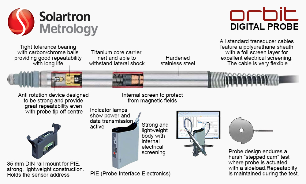
Probe Interface Electronics.
Pre-Travel
The mechanical movement from the fully outward position, where the moving element is against a mechanical limit stop, to the start of the measurement range.
Post-Travel
The mechanical movement from the end of the measurement range to the fully inward position, where the moving element is against a mechanical limit stop. Total mechanical range is always greater than measuring range.
______________________________________________________________________________________________________
R
Repeatability is defined as the ability of the transducer to provide measurements within a close distribution on the same measured carried out in the same direction.
Solartron uses a method of establishing repeatability where a defined side load is applied to the transducer under test which reflects how transducers are used in most real applications. Methods of measuring repeatability with out applying side load usually give a better result but this may not be reflected in real life applications.
The minimum voltage attained for the electrical zero position, i.e. the smallest output that can be detected.
______________________________________________________________________________________________________
S
This is the specified magnitude of the output with repect to displacement (mm) and energising voltage (V) for a LVDT or Half Bridge transducer. It is expressed in mV/V/mm.
______________________________________________________________________________________________________
T
A three way connector containing an E PROM to provide the address of a sensor or module in the Orbit® Network
The tip force of the transducer is defined as the force excreted on the sample at the electrical zero of the transducer or at the mid point of the measurement range for Digital Transducers and linear encoders
Total Mechanical Range
The distance over which the moving part of a transducer can be placed between two physical end stops. Total mechanical range is always greater than measuring range.
______________________________________________________________________________________________________
U
Uncertainty is an issue that is associated with any measurement. At Solartron Metrology, the GUM (Guide for the Expression of Uncertainties in Measurement) is used to specify the uncertainties of verification of its products. This section discusses uncertainty for the different product categories.
Analogue Gauging Products are verified using a variety of instruments such as an optical Linear Encoder, a barrel micrometer or wedge comparator. The verification using an optical Linear Encoder results in an uncertainty of better than 0.5μm.
Digital Products and analogue and digital linear encoder are verified using an optical interferometer, the wavelength of which is computed using Edlen's formula (B. Edlen, Metrologia Vol. 2, 71 (1996)) for operation under the normal atmospheric conditions (not a vacuum).
The uncertainty of the measurement is usually less that 0.1 μm.
The user should refer to the verification or calibration sheets for actual verification or calibration sheets for actual values.
|