|
|
 |
|
|
 |
|
|
|
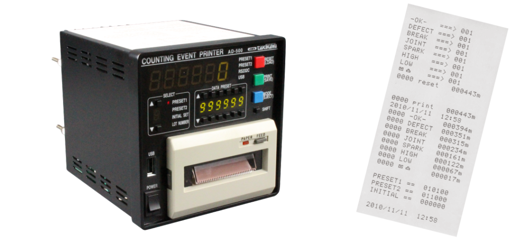
Counting event printer AD series
|
|
It receives alarm signals from various devices such as outer diameter measuring instruments and unevenness detectors, and continuously prints the wire distance and message at the time of reception.
Preset values (forecast/full) can be set for measured values, and alarms can be output via the RS-232C I/F (standard equipment).
In addition, it is possible to scale the measurement pulse, and by setting the correction distance for each message, the accurate measurement value can be recorded.
Equipped with a USB port, data can be saved and event names can be changed from a USB memory.
|
|
|
|
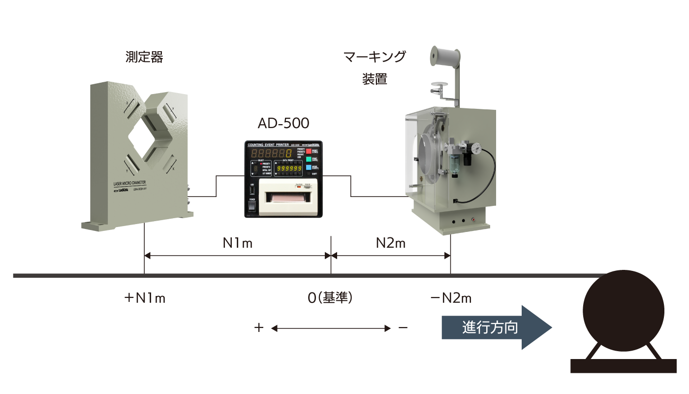
Event input distance correction setting mode
|
 |
|
By presetting the position of the measuring instrument that will be the event input source from the reference position, the distance of the measuring instrument or marking device can be corrected.
As a result, it is possible to mark the exact position as well as print the exact measured value at the time of event occurrence.
|
|
|
|
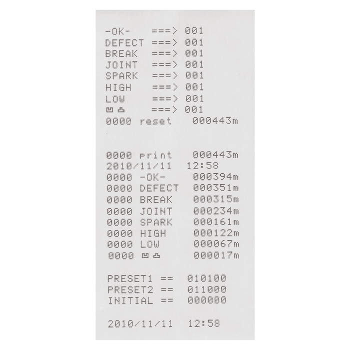
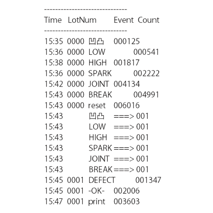
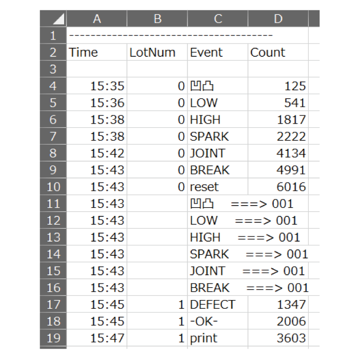
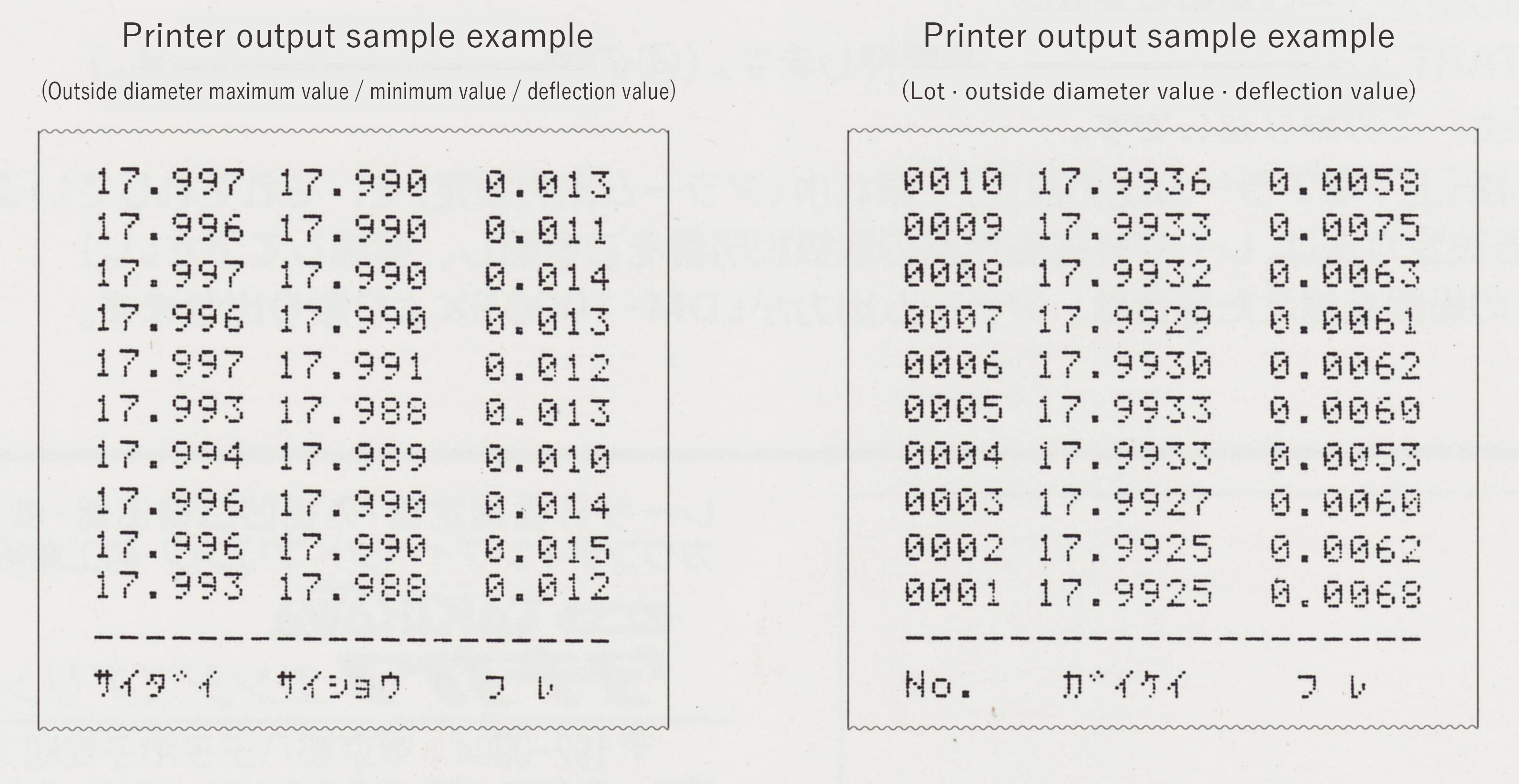
Data output example
|
|
You can enter up to 10 types of messages, including date, time and lot number.
Various settings including the clock can be saved for a long time by battery backup.
|
|
|
 |
|
 |
|
 |
thermal paper
|
|
TXT format
|
|
CSV format
|
|
|
|
|
Specification
|
|
model name |
AD-500 |
|
CAD file |
 |
 |
|
Measuring function |
scale display |
6-digit green/red 2-color 7-segment LED |
|
Input clock for scale |
Supports single-phase pulse/A-phase B-phase pulse, up/down count possible |
|
clock pulse rate |
Maximum 2kPPS/100PPS selectable |
|
pulse rate |
Can be set arbitrarily within the range of 0.00001 to 999999m/pulse |
|
Scale sensor power supply |
DC+12V Max.70mA |
|
event input |
Number of event messages |
10 types |
|
Message event input |
Rear terminal block |
|
Reset event input |
Front panel switch, rear terminal block, RS-232C |
|
print event input |
Front panel switch, rear terminal block, RS-232C |
|
Rename message event |
Changeable via RS-232C/USB memory |
|
various settings |
Various parameter settings |
Digital setting by 6-digit green 7-segment LED |
|
PRESET1 (full) |
6 digits (absolute value setting) |
|
PRESET2 (Forecast) |
6 digits (absolute value setting or relative value setting to PRESET1 is also possible) |
|
Each PRESET output |
Measured value 7-segment red display, front panel LED, relay contact, RS-232C |
|
initial set |
6 digits |
|
lot number |
4 digits can be automatically updated |
|
Event input distance correction |
More accurate measurement is possible by setting the correction distance for each message event |
|
printing |
printer |
58mm width, 20 digits, thermal method |
|
No recording paper output |
Front panel LED, relay contact, RS-232C |
|
USB |
memory controller |
USB 2.0 host controller |
|
function |
Event data save function to USB memory, set value load/save function |
|
Marker output |
Relay contact output, pulse width can be set in units of 1 msec in the range of 0 to 60000 msec |
|
clock function |
year-month-day-hour-hour |
|
battery backup |
Backup scale, clock, and various settings (backup time: 1 month or more) |
|
external communication |
RS-232C standard equipment (baud rate 9600/19200bps) |
|
power supply |
AC90-240V free power supply 50/60Hz |
|
power consumption |
8 VA or less |
|
|
|
|
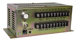
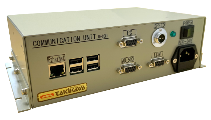
Communication unit AD-COM
|
 |
|
It is used by connecting with our company's laser outer diameter measuring instrument and counting event printer.
By inputting the line speed control voltage, the date/time/measurement value/outer diameter value/line speed/event name at the time of event occurrence are recorded, and the date/time/measurement value/outer diameter value/line speed is recorded every 5 seconds. record.
Recorded data is saved in CSV format on a LAN-connected computer.
|
|
|
|
|
|
 |
|
|
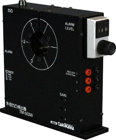
TM / Surface Variation Detector
|
|
|
|
Fine wire counterpart (Measurement object diameter: Φ 0.02 to 3 mm, 0.02 to 5 mm) |
|
Model No. |
TM-503W |
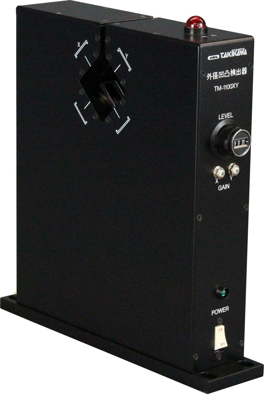
TM-1100XY |
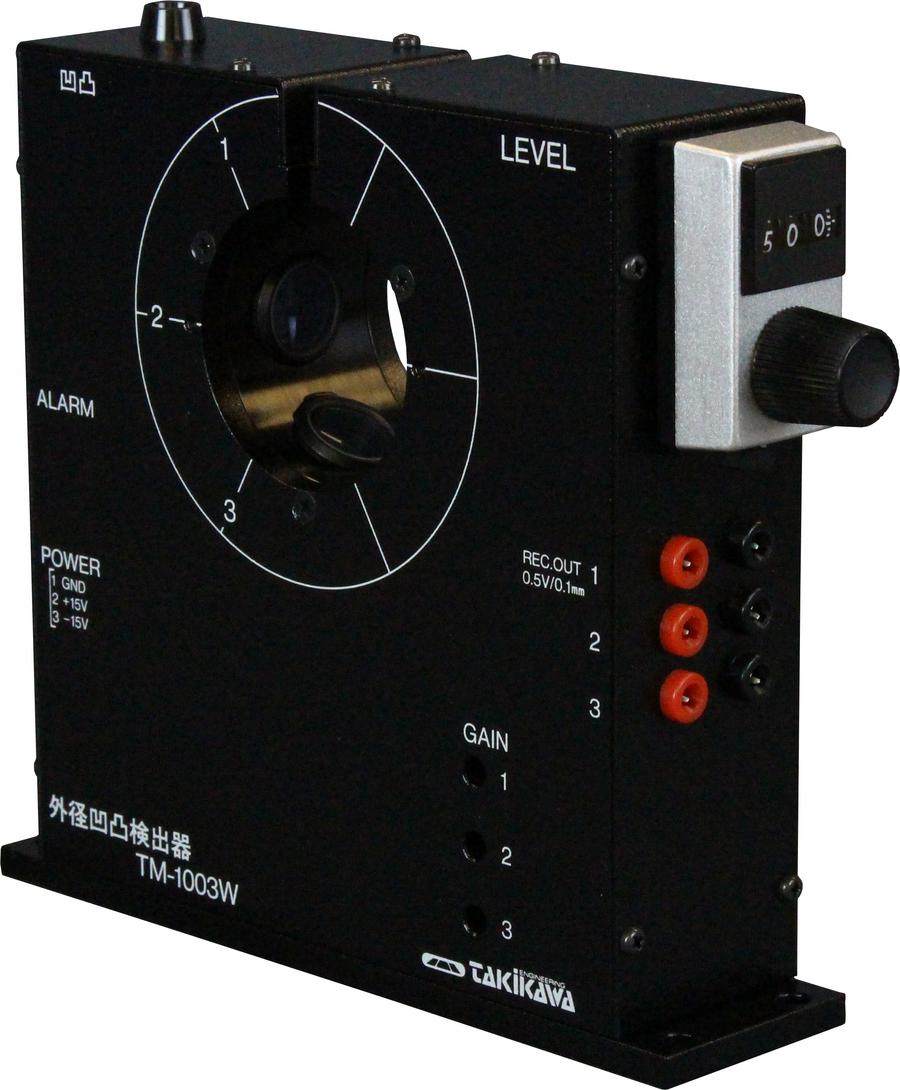
TM-1003W |
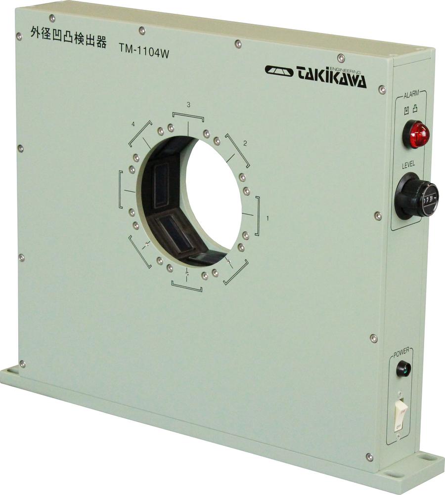
TM-1104W |
|
CAD file |

Power supply unit (PW-02)
[*1] |
|
Power supply unit (PW-01)
[*1] |
|

Power supply unit (PW-02)
[*1] |
|
Power supply unit (PW-01)
[*1] |
|
|
Direction of detection |
3 directions |
2 directions |
3 directions |
4 directions |
|
Measurement method |
Double slit infrared LED projection type |
|
Adaptive work outer diameter |
φ0.02 to 3 mm |
φ0.02 to 10 mm |
φ0.02 to 5 mm |
φ0.02 to 10 mm |
|
Unevenness detection range |
0.02 to 1 mm |
|
Unevenness detection accuracy |
Maximum setting within ± 1% |
|
Slit length |
6 mm |
18 mm |
12 mm |
18 mm |
|
Slit width |
0.1 mm |
0.5 mm |
|
Linear speed [*1] |
5 m / min to 2000 m / min |
1 m / min to 1500 m / min |
|
Recorder output |
± 0.2 V / 0.1 mm |
± 1 V / 0.1 mm |
± 0.5 V / 0.1 mm |
± 1 V / 0.1 mm |
|
Alarm output |
Uneven red LED lit, Relay contact output (AC 250 V 2A resistive load) |
|
Alarm time [*2] |
0.1 seconds |
0.5 seconds |
0.1 seconds |
0.5 seconds |
|
Operating temperature |
-5 to 50 ° C (without condensation) |
|
Power supply [*3] |
DC ± 15 V |
AC 100V
50/60 Hz |
DC ± 15 V |
AC 100V
50/60 Hz |
|
Power consumption |
6VA |
10VA |
6VA |
10VA |
|
Outline Dimensions (mm) |
150 × 140 × 40 |
260 × 265 × 60 |
150 × 140 × 40 |
350 × 280 × 55 |
|
Weight |
0.8kg |
2.5kg |
1kg |
5kg |
[*1] PW-01 is a power supply dedicated to TM-1003W.PW-02 is a power supply for both TM-503W and TM-1003W.
(The enclosures are the same size for PW-01 and PW-02.)
[*2] Applicable line speed range changes depending on the hight of lump.
[*3] Alarm output can be hold by option
[*4] AC200V power supply specification is also available as an option.
|
Medium wire counterpart (Measurement object diameter: Φ 0.1 to 35 mm) |
|
Model No. |
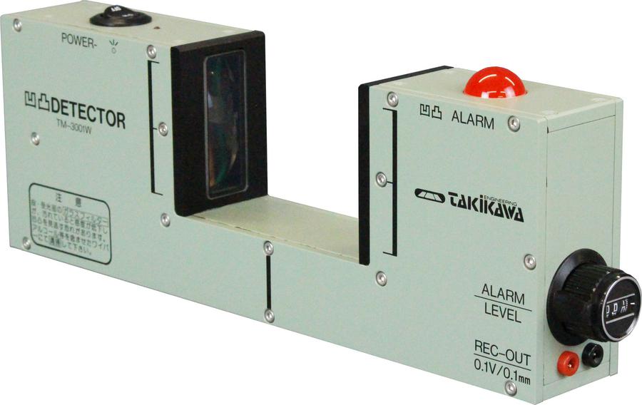
TM-3001W |
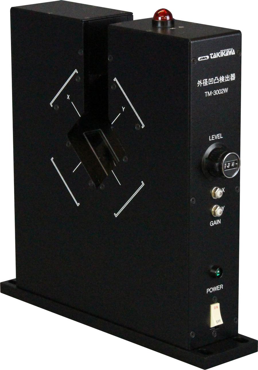
TM-3002W |
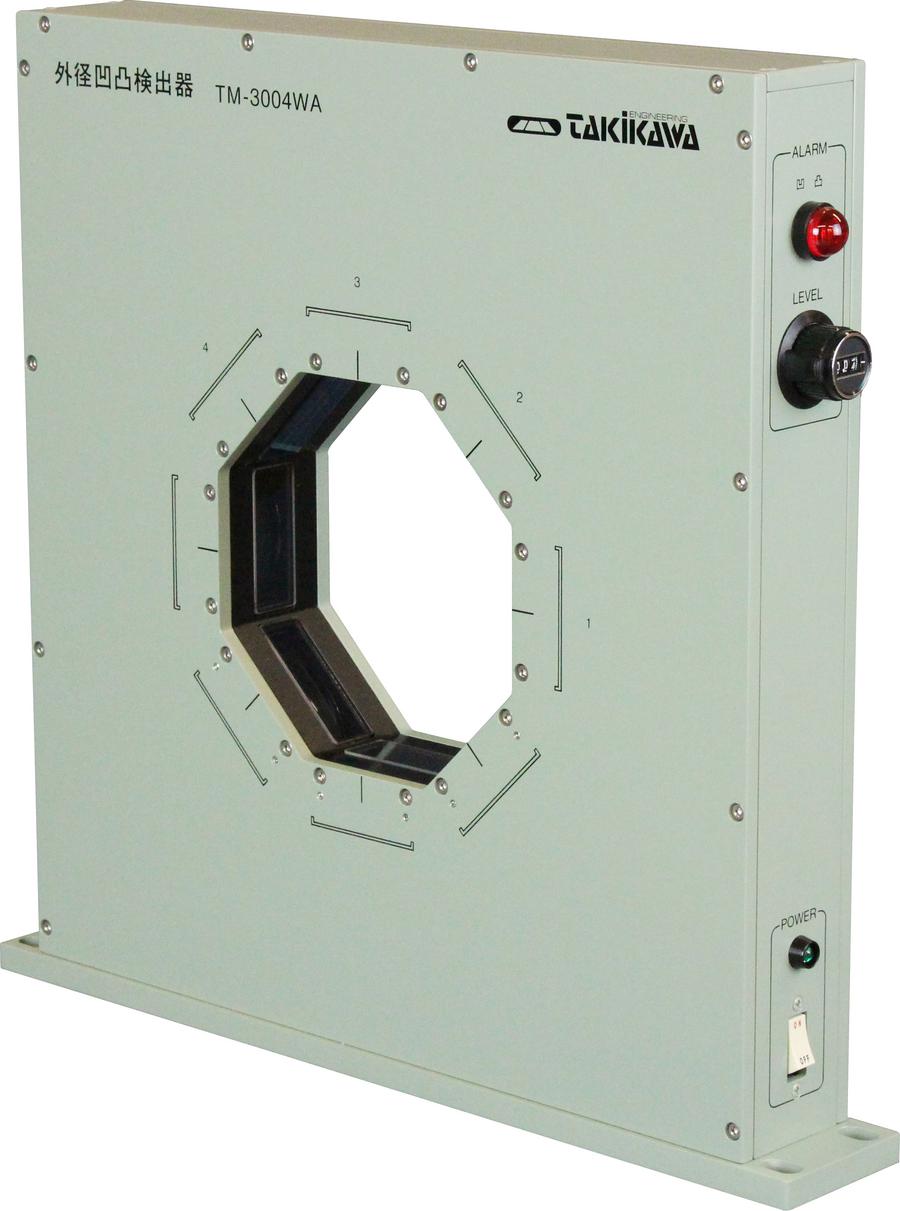
TM-3004WA |
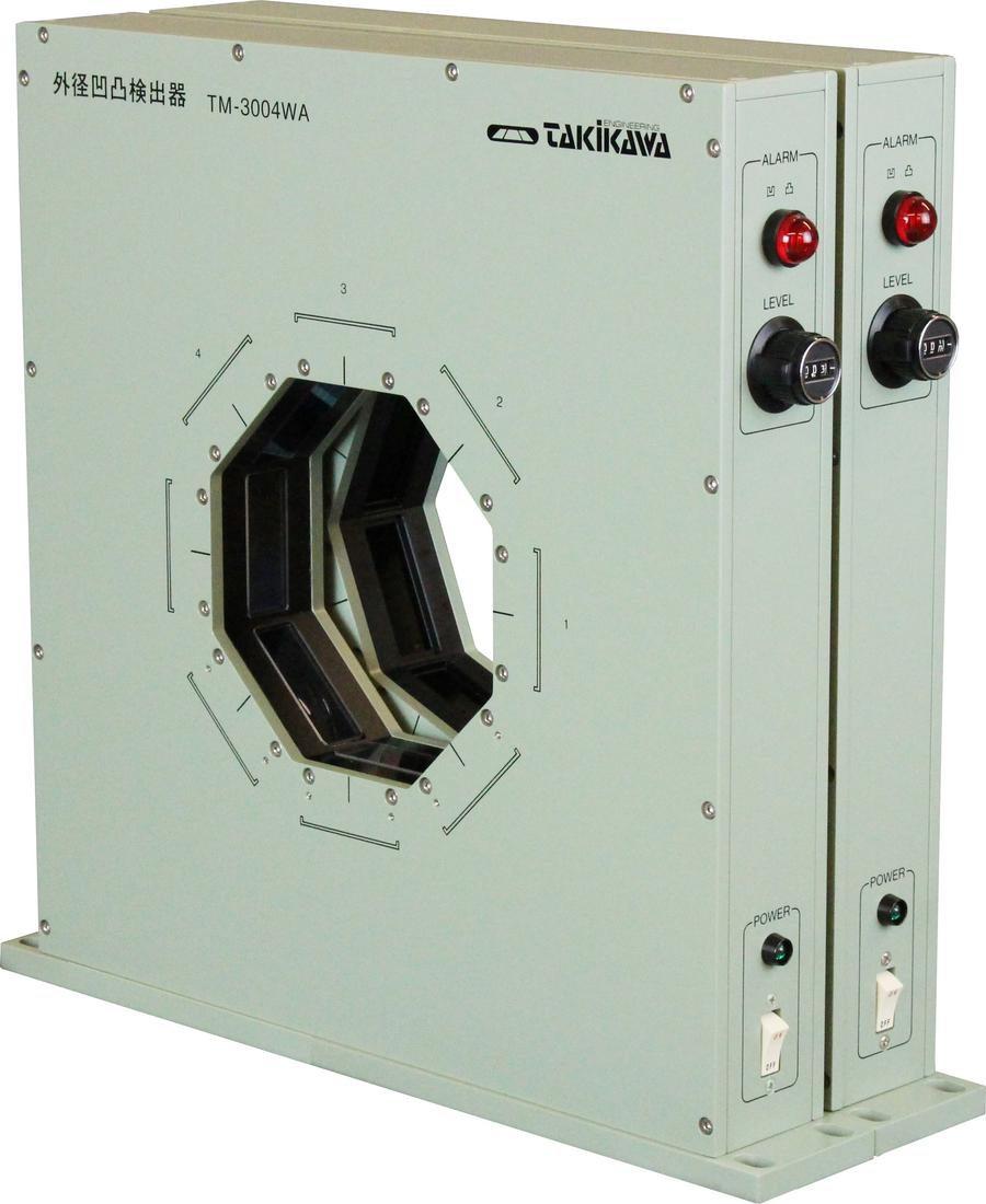
TM-3008W
(TM-3004WA)
(TM-3004WB) |
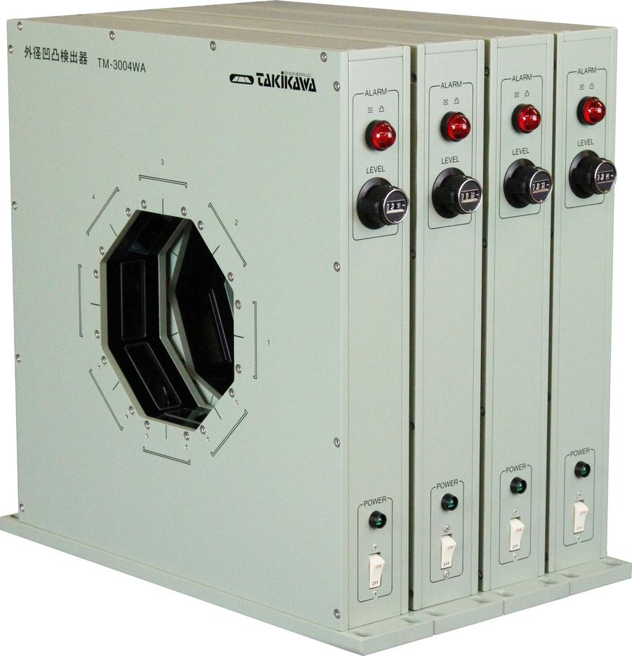
TM-3016W
(TM-3004WA)
(TM-3004WB)
(TM-3004WC)
(TM-3004WD) |
|
CAD file |
|
|
|
|
|
|
|
|
|
|
|
|
Direction of detection |
1 direction |
2 directions |
4 directions |
8 direction |
16 directions |
|
Measurement method |
Double slit infrared LED projection type |
|
Adaptive work outer diameter |
φ 0.1 - 35 mm |
|
Unevenness detection range |
0.05 to 10 mm |
|
Unevenness detection accuracy |
Maximum setting within ± 1% |
|
Slit length |
48 mm |
|
Slit width |
1 mm |
|
Linear speed [*1] |
1 m / min to 1500 m / min |
|
Recorder output |
± 0.1 V / 0.1 mm (for each axis) |
|
Alarm output |
Uneven red LED lit, Relay contact output (AC 250 V 2A resistive load) |
|
Alarm time [*2] |
0.5 seconds |
|
Operating temperature |
-5 to 50 ° C (without condensation) |
|
Power supply [*3] |
AC 100 V 50/60 Hz |
|
Power consumption |
5VA |
10VA |
10VA |
20VA |
40VA |
|
Outer dimension |
260 × 90 × 41 [mm] |
260 × 260 × 60 [mm] |
370 × 355 × 60 [mm] |
370 × 355 × 120 [mm] |
370 × 355 × 240 [mm] |
|
Weight |
1.5kg |
3kg |
6kg |
12kg |
24kg |
[*1] Applicable line speed range changes depending on the hight of lump.
[*2] Alarm output can be hold by option
[*3] AC200V power supply specification is also available as an option.
|
Bold wire counterpart (Measurement object diameter: Φ 0.1 to 60 mm) |
|
Model No. |
TM-4001 |
TM-4002 |
TM-4004A |
TM-4008
(TM-4004A)
(TM-4004B) |
TM-4016
(TM-4004A)
(TM-4004B)
(TM-4004C)
(TM-4004D) |
|
CAD file |
|
|
|
|
|
|
|
|
|
|
|
|
Direction of detection |
1 direction |
2 directions |
4 directions |
8 direction |
16 direction |
|
Measurement method |
Infrared LED projection type |
Double slit infrared LED projection type |
|
Adaptive work outer diameter |
φ 0.1 - 60 mm |
|
Unevenness detection range |
0.05 to 10 mm |
0.15 to 10 mm |
|
Unevenness detection accuracy |
Maximum setting within ± 1% |
Maximum setting within ± 2% |
|
Slit length |
70mm |
|
Slit width |
1.5mm |
|
Linear speed [*1] |
1 m / min to 1000 m / min |
|
Recorder output |
± 0.1 V / 0.1 mm (for each axis) |
|
Alarm output |
Alarm red LED on, Relay contact output (AC250V 2A resistive load) |
LED lighting (concave: yellow / convex: red), relay contact output (AC 250 V 2A resistive load unevenness output separately) |
|
Alarm time [*2] |
0.5 seconds |
|
Operating temperature |
-5 to 50 ° C (without condensation) |
|
Power supply [*3] |
AC 100 V 50/60 Hz |
|
Power consumption |
10VA |
20VA |
30VA |
60VA |
120VA |
|
Outer dimension |
450 * 120
× 50 [mm] |
640 * 560
× 160 [mm] |
807 * 674
× 136 [mm] |
807 * 674
× 272 [mm] |
807 × 680
× 424 [mm] |
|
Weight |
3kg |
25kg |
38kg |
76kg |
152kg |
[*1] Applicable line speed range changes depending on the hight of lump.
[*2] Alarm output can be hold by option
[*3] AC200V power supply specification is also available as an option.
|
Applicabe to extra thick wire (Measurement object diameter: Φ 1 mm to 80 mm, 1 to 130 mm) |
|
Model No. |
TM-6004A |
TM-6008
(TM-6004A)
(TM-6004B) |
TM-7003A |
TM-7009
(TM-7003A)
(TM-7003B)
(TM-7003C) |
|
CAD file |
|
|
|
|
|
|
|
|
|
|
Direction of detection |
4 directions |
8 direction |
3 directions |
9 direction |
|
Measurement method |
Single slit white tungsten lamp floodlight type |
|
Adaptive work outer diameter |
φ 1 to 80 mm |
φ1 to 130 mm |
|
Unevenness detection range |
0.2 to 10 mm |
|
Unevenness detection accuracy |
Maximum setting value within ± 2% |
|
Slit length |
95 mm |
135 mm |
|
Slit width |
1.5 mm |
|
Linear speed [*1] |
0.3 m / min to 500 m / min |
|
Recorder output |
± 0.1 V / 0.1 mm (for each axis) |
|
Alarm output |
LED lighting (concave: yellow / convex: red), relay contact output (AC 250 V 2A resistive load unevenness output separately) |
|
Alarm time [*2] |
0.5 seconds |
|
Operating temperature |
-5 to 50 ° C (without condensation) |
|
Power supply [*3] |
AC 100 V 50/60 Hz |
|
Power consumption |
30VA |
60VA |
30VA |
90VA |
|
概略外寸 |
720 x 660
× 153 [mm] |
720 × 660
× 306 [mm] |
990 × 930
× 125 [mm] |
990 × 930
× 375 [mm] |
|
Weight |
38kg |
76kg |
60kg |
180kg |
[*1] Applicable line speed range changes depending on the hight of lump.
[*2] Alarm output can be hold by option
[*3] AC200V power supply specification is also available as an option.
In addition to this, you can also prepare products such as TM-6020 (20 axis) and other multi-axis products.
|
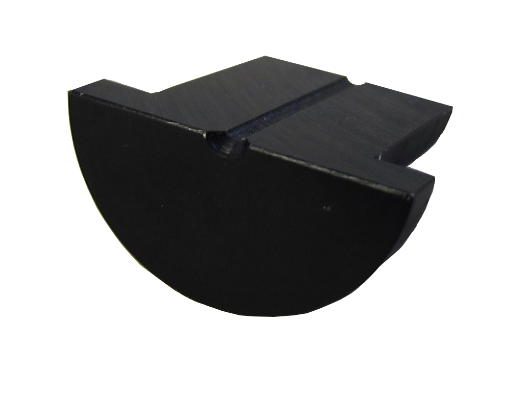
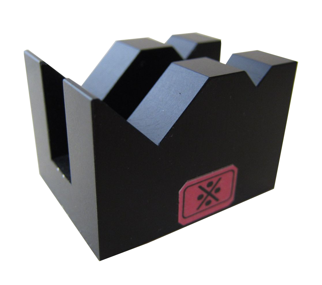
Gauge Fixture / Calibration gauge unit for Surface Variation Detector
|
Calibration gauge unit
|
Gauge outer diameter (mm) |
Model |
Accuracy |
|
Φ1.0 |
TMG-10 |
±1μm |
|
Φ0.5 |
TMG-05 |
±1μm |
Note) It can be available down to Φ0.1.
Gauge Fixture and corresponding gauge unit table
|
Target Model |
Calibration gauge to use |
Mounting jig type |
|
TM-1000S |
TMG-05 |
01 |
|
TM-1003 |
TMG-05 |
02 |
|
TM-1000XY |
TMG-05 |
03 |
|
TM-1004 |
TMG-05 |
04 |
|
TM-1100XY |
TMG-05 |
05B |
|
TM-1003W |
TMG-05 |
06B |
|
TM-1104W/TMS-1104W |
TMG-05 |
07B |
|
TM-503W |
TMG-01 |
16B |
|
TM-3001W |
TMG-10 |
08B |
|
TM-3002W |
TMG-10 |
09 |
|
TM-3004W |
TMG-10 |
10B |
|
TM-3008W |
TMG-10 |
10B |
|
TM-3016W |
TMG-10 |
10B |
|
TM-4001/4001W |
TMG-10 |
---- |
|
TM-4002 |
TMG-10 |
12B |
|
TM-4002W |
TMG-10 |
17B |
|
TM-4004 |
TMG-10 |
13B |
|
TM-4008 |
TMG-10 |
13B |
|
TM-4016 |
TMG-10 |
13B |
|
TM-6004 |
TMG-10 |
14B |
|
TM-6008 |
TMG-10 |
14B |
|
TM-6016 |
TMG-10 |
14B |
|
TM-7003 |
TMG-10 |
15B |
|
TM-7009 |
TMG-10 |
15B |
|
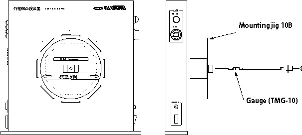
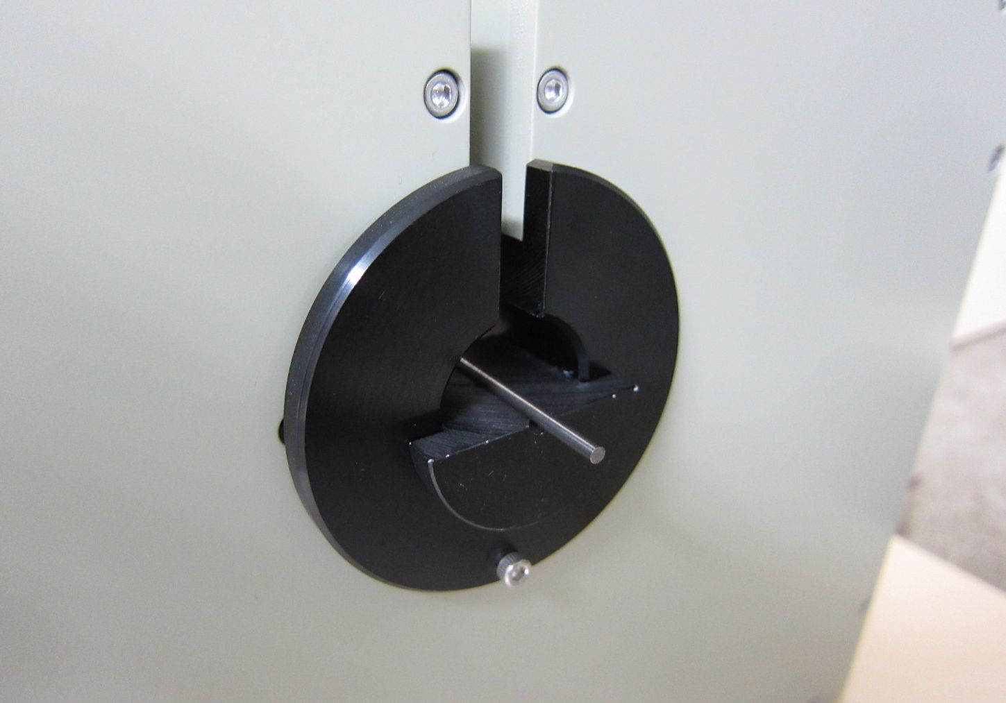
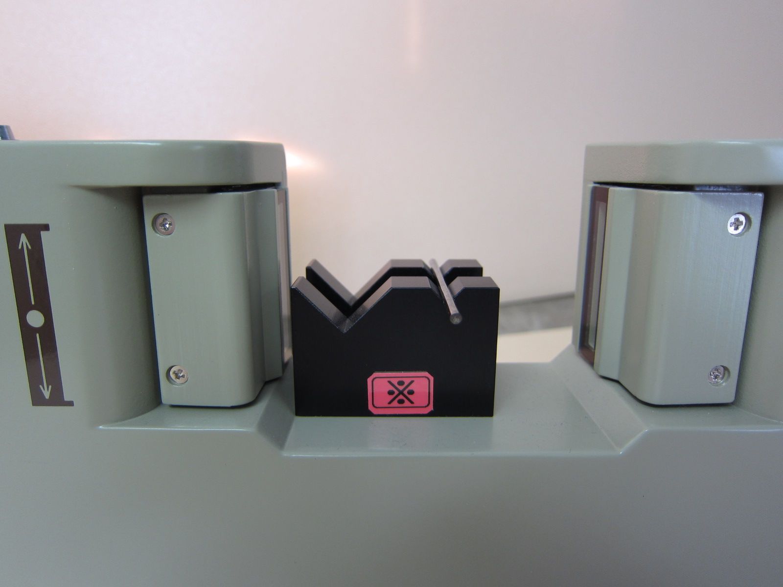
Example of calibration method (TM-3004W)
|
 |
|
|
|
Although our detectors are calibrated at the time of shipment, when it is necessary to perform calibration for checking the sensitivity at the time of inspection etc., please perform calibration according to the following method with the calibration gauge unit. The calibration gauge unit to be used is "TMG - 10, Gauge Fixture 10B".
** Before calibration, please be sure to clean the glass filter of the projecting / receiving part and warm up for 10 minutes.
I will explain with 1 axis as an example.
-
Set the Gauge Fixture according to the axis for calibration (this time, 1 axis). (The figure below)
-
Set the level setting dial to "1.00".
-
Insert the gauge tip quickly into the center of the measuring range. At this time, please insert gauge so as not to be inclined as much as possible.
-
When the gauge tip is inserted while repeating the insertion several times, adjust the gain setting VR of 1 axis the lowest to light up the detection alarm lamp.(herein after lamp)
* It is not abnormal although the lamp may light up when extracting the tip of the gauge.
* Set an interval of about 3 seconds after the lamp is turned off when repeating the insertion of the gauge tip.
* VR for gain setting increases sensitivity when turned clockwise, and decreases when turning it counterclockwise.
-
Change the level setting dial to "1.03".
-
Repeat the insertion of the gauge tip in the same way.Now adjust the VR for 1 axis gain adjustment so that the lamp does not light up when inserting the tip of the gauge.
-
The calibration will be completed after repeating steps (2) - (6) several times to light up at "1.00" and not light up at "1.03".
|
For Thin Wire
|
|
|
|
|
|
|
Outer dimension[W * H * D] 150×140×40(mm)
TM-503W |
|
Outer dimension[W * H * D] 260×265×60(mm)
TM-1100XY |
|
Outer dimension[W * H * D] 150×140×40(mm)
TM-1003W |
|
|
|
|
|
|
|
|
|
|
|
|
Outer dimension[W * H * D] 350×280×55(mm)
TM-1104W |
|
|
|
|
|
|
|
For Medium Wire
|
|
|
|
|
|
|
Outer dimension[W * H * D] 260×90×41(mm)
TM-3001W |
|
Outer dimension[W * H * D] 260×260×60(mm)
TM-3002W |
|
Outer dimension[W * H * D] 370×335×60(mm)
TM-3004WA |
|
|
|
|
|
|
|
|
|
|
|
|
|
TM-3008W |
|
TM-3016W |
|
|
|
|
|
For Thick Wire
|
|
|
|
|
|
|
Outer dimension[W * H * D] 540×160×100(mm)
TM-4001 |
|
Outer dimension[W * H * D] 630×560×160(mm)
TM-4002 |
|
Outer dimension[W * H * D] 807×674×136(mm)
TM-4004 |
|
|
|
|
|
|
|
|
|
|
|
|
|
TM-4008 |
|
TM-4016 |
|
|
|
|
|
|
|
Applicabe to extra thick wire
|
|
|
|
|
|
|
Outer dimension[W * H * D] 720×660×153(mm)
TM-6004A |
|
TM-6008 |
|
TM-7003A |
|
|
|
|
|
|
|
|
|
|
|
|
|
TM-7009 |
|
|
|
|
|
|
|
|
|
|
|
|
|
Laser Micrometer ・ Scanning Unit specification list
|
400 scan type
|
|
Common specification |
|
Measurement method |
Non-contact laser scanning method |
|
Light source |
Semiconductor laser (up to 1 mW), red (670 nm), Class 2 continuous wave |
|
Protective structure |
Dustproof structure (IP-64) |
|
Operating environment |
Temperature 0 to 45 ° C Humidity 35 to 85% RH (without condensation) |
|
Individual specification |
|
Type |
Model No. |
Measurement range (mm) [*1] |
Measurement accuracy[*2] |
Resolution |
Weight |
CAD file |
|
1 axis measurement |
Standard type |
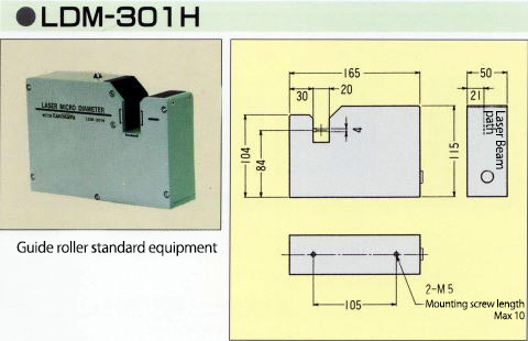
LDM-301H |
0.02 to 1 |
±1μm |
±0.1μm |
1kg |
|
|
|
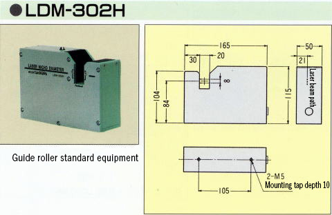
LDM-302H |
0.05 to 5 |
±1μm |
±0.1μm |
1kg |
|
|
|
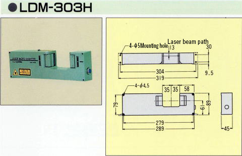
LDM-303H |
0.3 to 30 |
±2μm |
±0.1μm |
1kg |
|
|
|
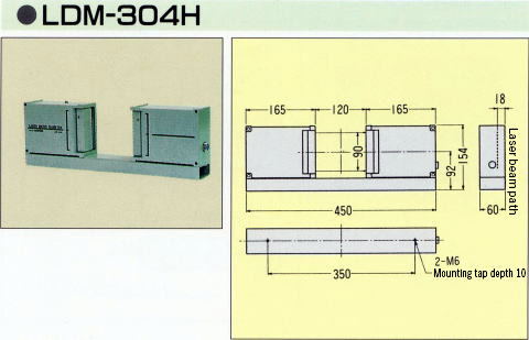
LDM-304H |
0.5 to 90 |
±5μm |
±1μm |
2.9kg |
|
|
|
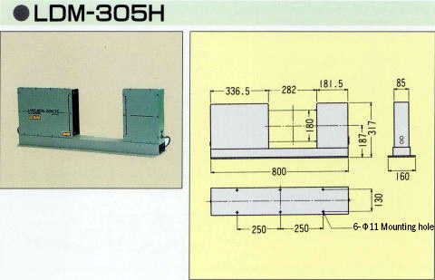
LDM-305H |
1 to 180 |
±10μm |
±1μm |
15kg |
|
|
|
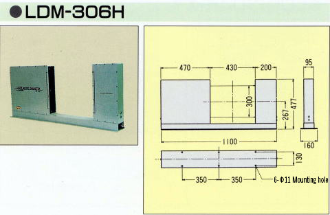
LDM-306H |
2 to 300[*2] |
±30μm |
±1μm |
34kg |
|
|
|
Separate type |
LDM-302H-SP |
0.05 to 5 |
±1μm |
±0.1μm |
1kg |
|
|
|
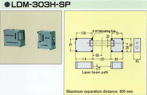
LDM-303H-SP |
0.3 to 30 |
±2μm |
±0.1μm |
0.9kg |
|
|
|
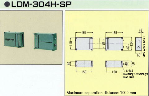
LDM-304H-SP |
0.5 to 90 |
±5μm |
±1μm |
2.3kg |
|
|
|
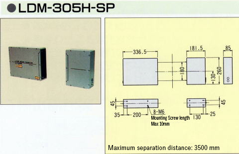
LDM-305H-SP |
1 to 180 |
±10μm |
±1μm |
11kg |
|
|
|
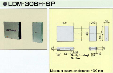
LDM-306H-SP |
2 to 300[*2] |
±30μm |
±1μm |
28kg |
|
|
|
Orthogonal two-axis measurement |
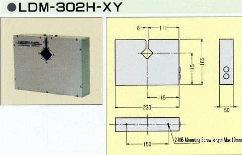
LDM-302H-XY |
0.05 to 5 |
±1μm |
±0.1μm |
2kg |
|
|
|
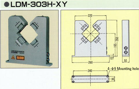
LDM-303H-XY |
0.3 to 30 |
±2μm |
±0.1μm |
2kg |
|
|
|
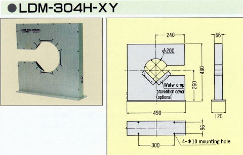
LDM-304H-XY |
0.5 to 90 |
±5μm |
±1μm |
14kg |
|
|
|
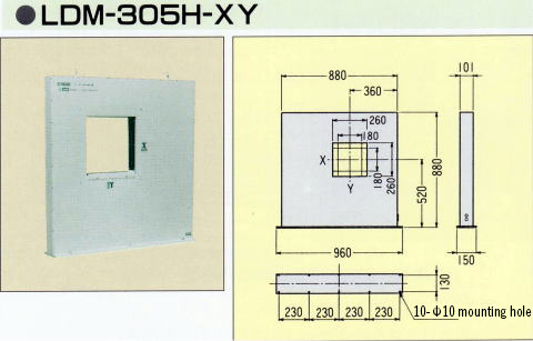
LDM-305H-XY |
1 to 180 |
±10μm |
±1μm |
50kg |
|
|
|
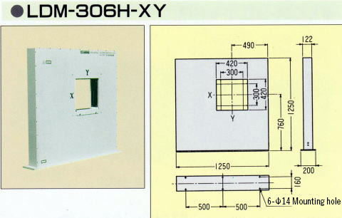
LDM-306H-XY |
2 - 300 |
±30μm |
±1μm |
70kg |
|
|
|
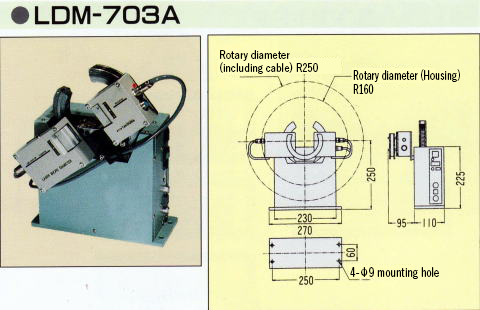
Oscillating type all-round measurement[*3] |
LDM-303H-SP
LDM-703A |
0.3 to 30 |
±2μm |
±0.1μm |
9kg[*4] |
|
|
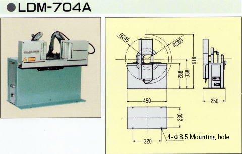
LDM-304H
LDM-704A |
0.5 to 90 |
±5μm |
±1μm |
27kg[*4] |
|
|
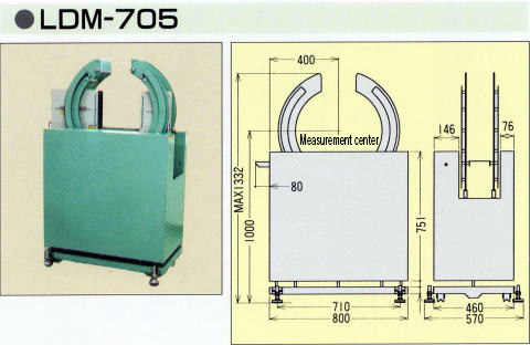
LDM-305H
LDM-705 |
1 to 180 |
±10μm |
±1μm |
60kg[*4] |
|
|
[*1]There is also a large diameter measuring system that can measure a larger diameter object.
[*2]Measurement accuracy, when you set the average number of times in a specific area to 256 times or more.
[*3]LDM-703A, 704A, 705 are the models of the swinging mechanism unit alone.
[*4]These weights are the weight of swinging mechanism unit alone.
|
2000 scan type
|
|
Common specification |
|
Measurement method |
Non-contact laser scanning method (2000 times / second sample) |
|
Light source |
Semiconductor laser (up to 1 mW), red (670 nm), Class 2 continuous wave |
|
Protective structure |
Dustproof structure (IP-64) |
|
Operating envirornment |
Temperature 0 to 45 ° C Humidity 35 to 85% RH (without condensation) |
|
Individual specification |
|
Type |
Model No. |
Measurement range (mm) |
Measurement accuracy[*1] |
resolution |
Weight |
CAD file |
|
1 axis measurement |
Standard type |
LDM-301HS |
0.03 ~ 1 |
±1μm |
±0.1μm |
1kg |
|
|
|
LDM-302HS |
0.07 to 5 |
±1μm |
±0.1μm |
1kg |
|
|
|
LDM-303HS |
0.3 to 30 |
±2μm |
±0.1μm |
1kg |
|
|
|
LDM-304HS |
0.5 to 90 |
±5μm |
±1μm |
2.9kg |
|
|
|
Separate type |
LDM-303
HS-SP |
0.3 to 30 |
±2μm |
±0.1μm |
0.9kg |
|
|
LDM-304
HS-SP |
0.5 to 90 |
±5μm |
±1μm |
2.3kg |
|
|
[*1]Measurement accuracy, when you set the average number of times in a specific area to 256 times or more.
For other specifications, it will be the contents of the following.
For details, please contact our sales department.
Separation distance of Separated type
LDM-302H-SP --- 20mm Max
LDM-303H-SP --- 400mm Max
LDM-304H-SP --- 1000mm Max
LDM-305H-SP --- 3500mm Max
LDM-306H-SP --- 5000mm Max
High temperature object measurement --- Option up to 2000 ° C possible
Transparent object measurement --- Equipped as standard (Set by Display Unit)
Transparent film width measurement --- possible by option
|
Laser Micrometer Calibration gauge and Calibration gauge Fixture
|
|
|
|
Object model |
Calibration gauge Fixture |
Calibration gauge diameter (mm) |
|
Lo |
Hi |
|
LDM-301H |
Standard mounting |
Φ0.03 |
Φ1.0 |
|
LDM-302H |
Standard mounting |
Φ0.05 |
Φ5.0 |
|
LDM-302H-SP |
Optional |
Φ0.05 |
Φ5.0 |
|
LDM-302H-XY |
L-022 |
Φ0.05 |
Φ2.0 (Φ5.0) |
|
LDM-303H |
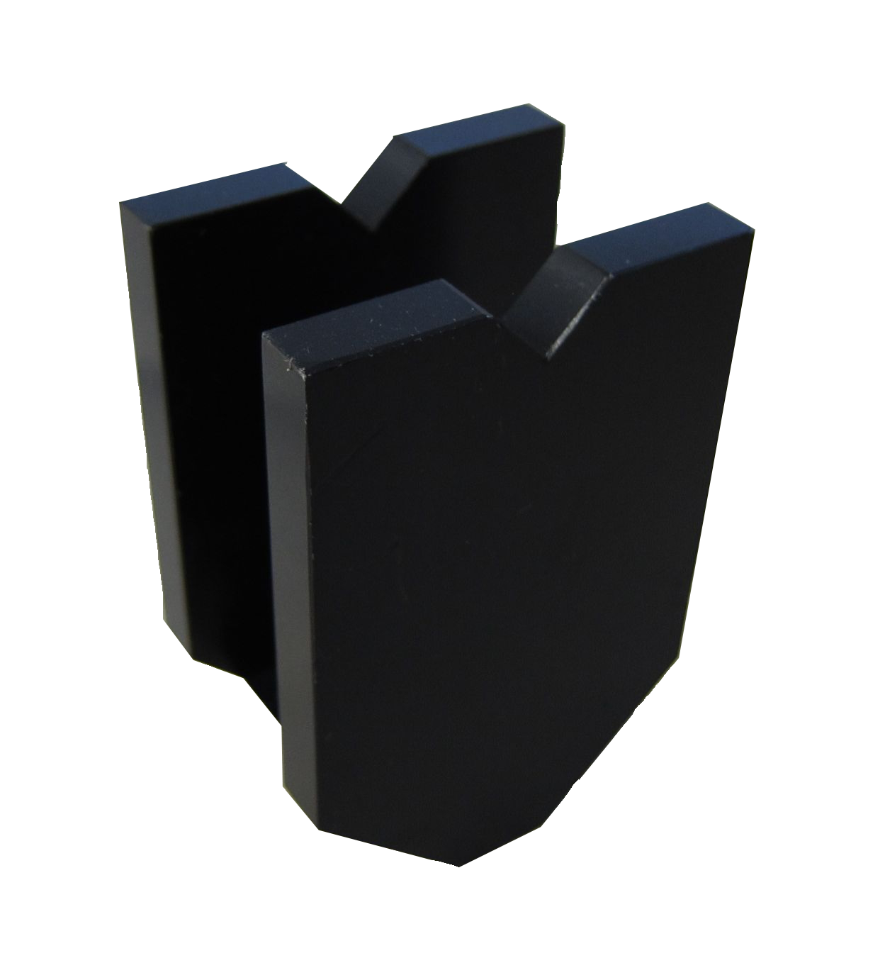
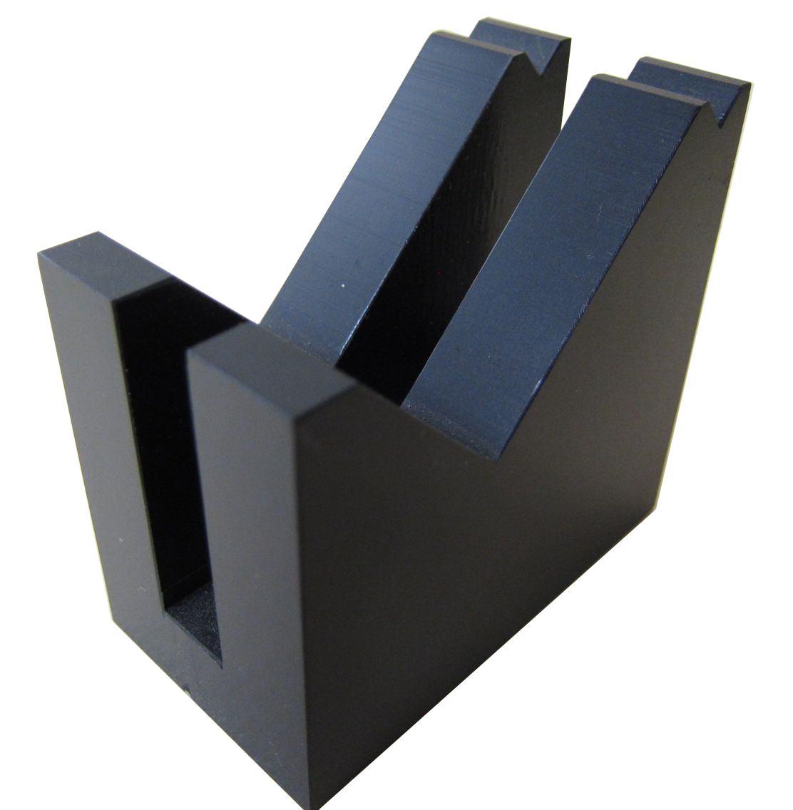
L-030[Photo] |
Φ0.3 |
Φ10.0 |
|
LDM-303H-SP |
Optional |
Φ0.3 |
Φ10.0 |
|
LDM-303H-XY |
L-032B[Photo] |
Φ0.3 |
Φ10.0 |
|
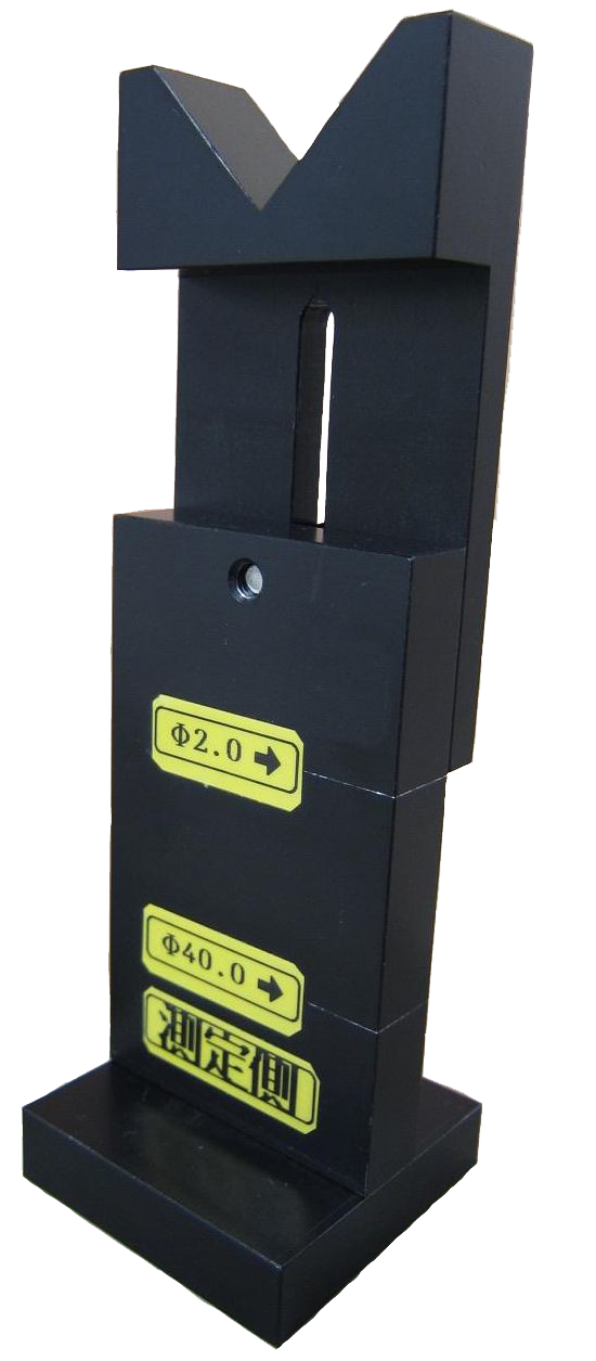
LDM-304H |
L-40 |
Φ2.0 |
Φ40.0 |
|
LDM-304H-SP |
Optional |
Φ2.0 |
Φ40.0 |
|
LDM-304H-XY |
L-042B[Photo] |
Φ2.0 |
Φ40.0 |
|
LDM-305H |
Optional |
Φ20.0 |
Φ100.0 |
|
LDM-305H-SP |
Optional |
Φ20.0 |
Φ100.0 |
|
LDM-305H-XY |
Optional |
Φ20.0 |
Φ100.0 |
|
LDM-306H |
Optional |
Φ20.0 |
Φ180.0 |
|
LDM-306H-SP |
Optional |
Φ20.0 |
Φ180.0 |
|
LDM-306H-XY |
Optional |
Φ20.0 |
Φ180.0 |
* Calibration gauge diameter can be changed according to customer's request.
* The gauge diameter stated in the calibration gauge diameter is the diameter used in standard products. Even if there is no diameter in this table, calibration may be possible if it is within the measurement range.
* Even not listed gauge diameters is also purchasable.
* Please contact our sales department for the detector with the description of the option on the calibration gauge table.
|
About actual calibration
|
|
|
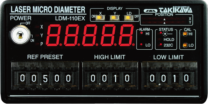
Example of calibration method with Laser Micrometer (LDM-110 / LDM-210)
|
|
It is not necessary to calibrate the Laser Micrometer it is already calibrated at the time of shipment.
When calibration is necessary, 2 point calibration is performed with large diameter and small diameter. So prepare 2 gauge pins with different reference outside diameter.
For example, the procedure when using a gauge pin of Φ 40 mm as a large diameter and Φ 5 mm as a small diameter is shown.
Suppose the decimal point display of the main display is set to the second from the left. (88.888 display)
-
Set REF PRESET to "40.000".
-
Set the gauge pin of Φ 40 mm as centered as possible in the measurement area of the Scanning Unit.
-
Push the HI switch of the CAL with a thing like a pin. (Please continue pushing for a while)
-
Release the CAL switch when the main display is displayed as "88888" and then "40000" is displayed. (This completes the calibration of Φ 40 mm)
-
Set REF PRESET to "05.000".
-
Set the gauge pin of Φ 5 mm as centered as possible in the measurement area of the Scanning Unit.
-
Push the LO switch of the CAL with a thing like a pin. (Please keep pushing for a while)
-
Release the CAL switch when it is displayed as "88888" and then "05000" on the main display. (This completes the calibration of Φ 5 mm)
This completes the calibration between Φ 5 and 40 mm.
|
LDM-301H
|
 |
|
|
LDM-302H
|
 |
|
|
LDM-303H
|
 |
|
|
 |
|
|
LDM-304H
|
 |
|
|
LDM-305H
|
 |
|
|
LDM-306H
|
 |
|
|
LDM-302HS
|
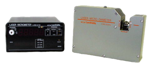 |
|
Outside Dimension : [W * H * D] LDM-210:144×72×191(mm)/ LDM-302HS:165×115×50(mm)
Left: LDM-210 / Right: LDM-302HS
|
|
|
LDM-302H-SP
|
 |
|
|
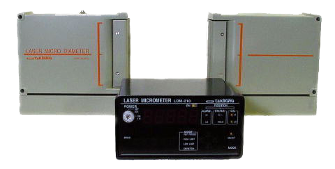
LDM-303HS
|
 |
|
Outside Dimension : [W * H * D] LDM-210:144×72×191(mm)/ LDM-303HS:289×89×45(mm)
Left: LDM-210 / Right: LDM-303 HS
|
|
|
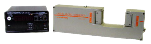
LDM-304HS
|
 |
|
Outside Dimension : [W * H * D] LDM-210:144×72×191(mm)/ LDM-304HS:450×154×60(mm)
Left: LDM-210 / Right: LDM-304 HS
|
|
|
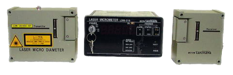
LDM-303HS-SP
|
 |
|
Outside Dimension : [W * H * D] LDM-210:144×72×191(mm)/ LDM-303HS-SP:Emitter 114×90×45(mm)& Receiver 80×90×45(mm)
Left: LDM-210 / Right: LDM-303 HS-SP
|
|
|
LDM-303H-SP
|
 |
|
Outside Dimension:[W * H * D] Emitter 114×90×45(mm)/ Receiver 80×90×45(mm)
|
|
|
LDM-304H-SP
|
 |
|
|
LDM-305H-SP
|
 |
|
|
LDM-306H-SP
|
 |
|
|
LDM-302H-XY
|
 |
|
|
LDM-303H-XY
|
 |
|
|
LDM-304H-XY
|
 |
|
|
LDM-305H-XY
|
 |
|
|
LDM-306H-XY
|
 |
|
|
LDM-703A
|
 |
|
|
LDM-704A
|
 |
|
|
LDM-705
|
 |
|
|
L-022(For LDM-302H-XY)
|
 |
|
 |
|
L-022(For LDM-302H-XY) |
|
Example of use |
|
|
|
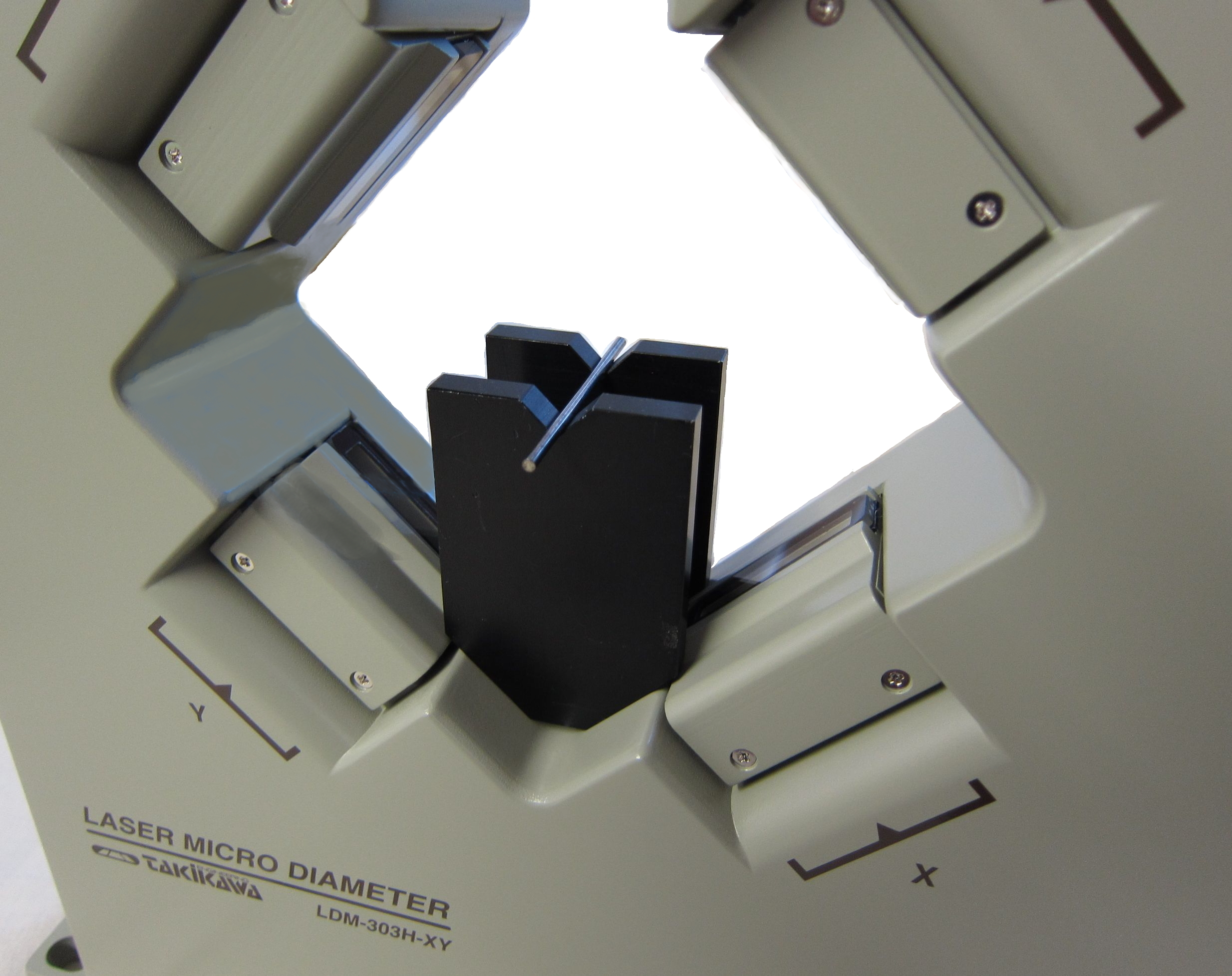
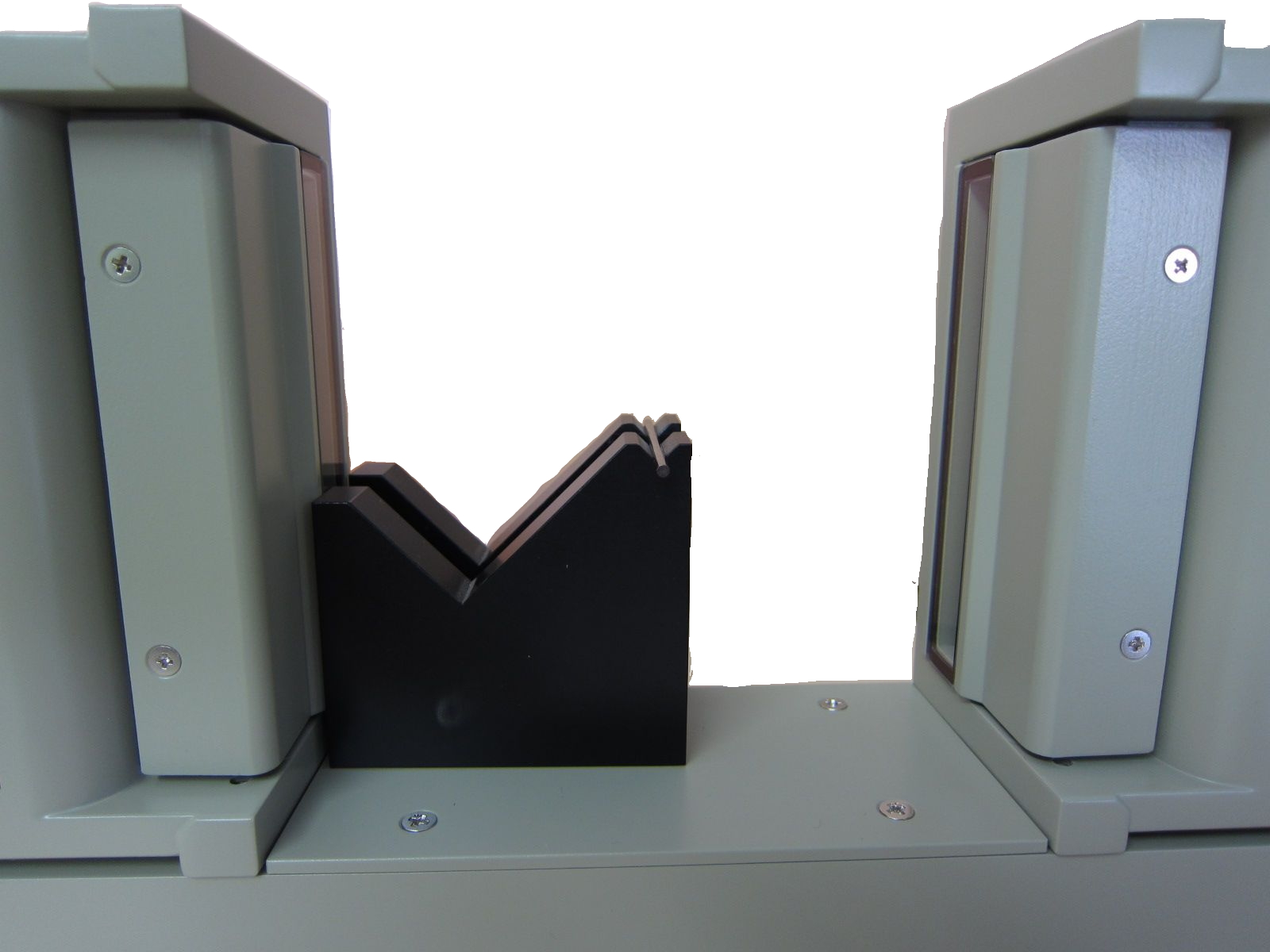
L-030(For LDM-303H)
|
 |
|
 |
|
L-030(For LDM-303H) |
|
Example of use |
|
|
|
L-032B(For LDM-303H-XY)
|
 |
|
 |
|
L-032B(For LDM-303H-XY) |
|
Example of use |
|
|
|
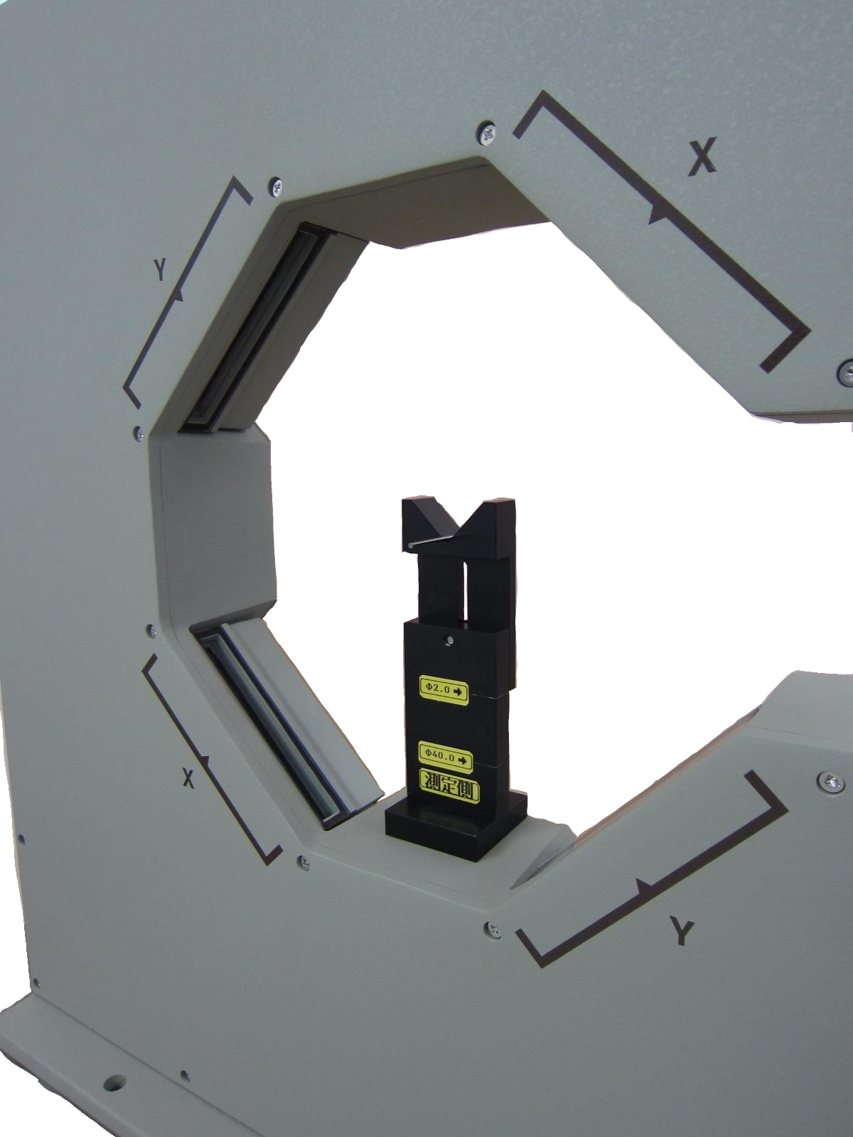
L-040(For LDM-304H)
|
 |
|
 |
|
L-040(For LDM-304H) |
|
Example of use |
|
|
|
L-042B(For LDM-304H-XY)
|
 |
|
 |
|
L-042B(For LDM-304H) |
|
Example of use |
|
|
|
Segnal Distributor / Signal Extender of Laser Micrometer
|
|
|
  |
|
|
LDM-B2
|
|
External dimension 200×150×80(mm)
|
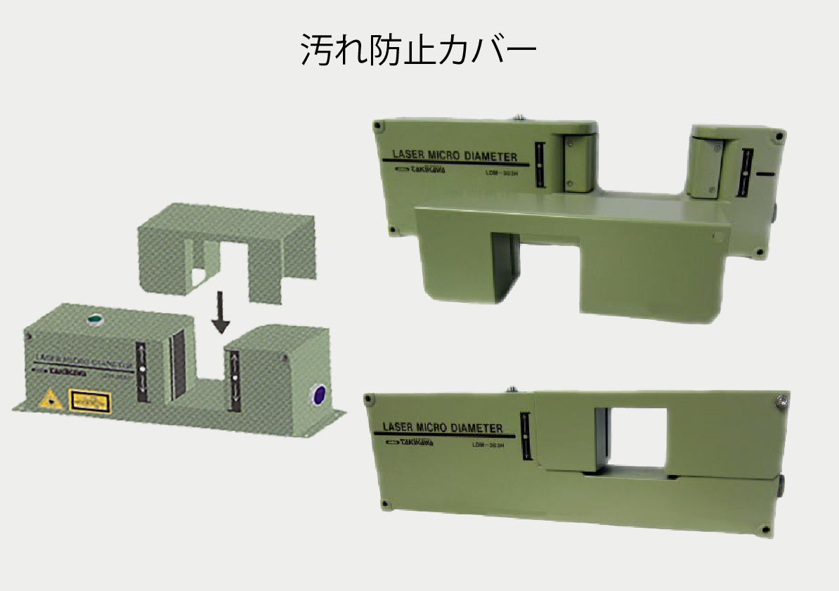
Air purge unit for Laser Micrometer
|
** Air purge units for LDM-303H, LDM-304H, LDM-303H-XY are available.**
This unit is a dustproof unit for preventing dirt from adhering to the glass filter surface of the Scanning Unit at a line with poor measurement conditions. When using, please put cleaned air from the compressor. For models not listed, please?contact our sales department. |
|
 |
|
|
|
Laser Micrometer ・ Display part specification list
|
|
|
400 scan type
|
|
|
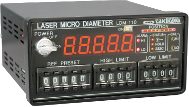
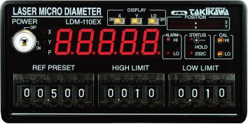
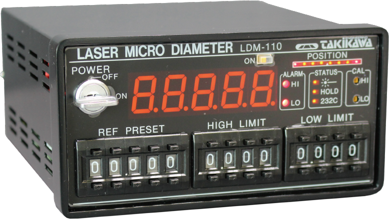
LDM-110
(Discontinued product) |
LDM-110EX
(Discontinued product) |
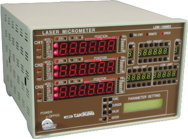
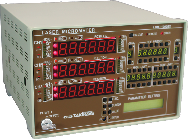
LDM-1000EX |
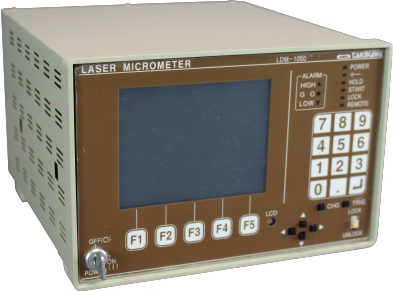
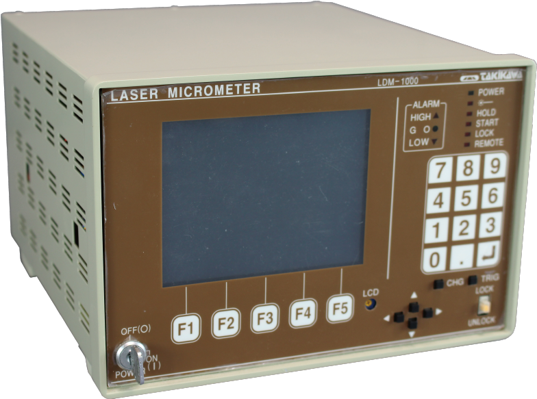
LDM-1000 |
|
CAD File |
|
|
|
|
|
|
|
|
|
|
Number of measurement axes |
1 Axis Only |
Up to 2 axes |
Up to 3 axes |
Up to 5 axes |
|
Number of samples |
400 times / sec |
400 times / sec |
400 times / sec |
400 times / sec |
|
Average times |
1 to 2048 times
(16 steps) |
1 to 2048 times
(8 steps) |
For LDM - 1000 LS, 1 to 2048 times (22 steps)
For LDM-1000XY 1 to 1024 times (19 steps) |
|
Measurement mode |
16 kinds |
8 types of each axis |
16 types of each axis + measurement between arbitrary edges |
|
Wall thickness calculation function |
- |
× |
Yes (possible with LDM-1000 XY) |
|
View |
Measured value display Device |
7 segment LED |
7 segment LED |
Graphic LCD |
|
Number of display digits |
5 digit |
6 digits |
6 digits |
|
Computation contents |
- |
["1", "average
2 "," difference
3 "," ratio
4 "," large caliber measurement "] |
["1", "average: (X + Y) / 2
2 "," Difference: X - Y
3 "," ratio: X / Y
4 "," (XY) / 2
5 "," X + Y
6 "," large caliber measurement "] |
|
Computation content display |
- |
○ |
○ |
○ |
|
Work position monitor |
Displayed in 8 LEDs |
Indicated by 8 axis LEDs |
Each axis graphic bar graph |
|
Analog output |
Number of output channels |
1 |
LDM-1000 LS and LDM-1000 XY
One channel for each board |
|
Output performance |
Maximum ± 10 V, resolution 12 bits (= about 10 mV resolution),
Output impedance approx. 100 Ω, deviation / absolute value changeable |
|
Output gain |
1 μm to 1 m / V (10 times step) |
0.1 μm to 1 m / V (10 times step) |
|
Digital outer diameter control connection |
○ |
○ |
× |
× |
|
Center value setting |
5 digit |
5 digit |
6 digits |
6 digits |
|
Upper / Lower limit tolerance setting |
4 digits |
4 digits |
5 digit |
6 digits |
|
Contact output |
Upper and lower limit contact outputs |
1 a contact × 2 |
LDM-1000 LS and LDM-1000 XY
1 "a" contact × 2 each board |
|
Error contact output |
1 b contact × 1 (Closed when power is OFF) |
1 "b" contact (closed at power off, 1 at full slot) |
|
Contact rating |
AC 250V 2A (resistance load) |
|
Laser remote terminal |
○ |
○ (Common to X / Y) |
○ (1 for each LDM-1000LS board) |
|
Hold terminal |
○ |
○
(Common to X / Y / P) |
○ (1 for each LDM-1000LS and LDM-1000XY board) |
|
Edge monitoring function |
○ |
○ |
○ |
○ |
|
Self-diagnosis function |
○ |
○ |
○ |
○ |
|
Multi-point calibration function |
○ |
No |
○
(Since ver.3.0) |
× |
Trigger function
(Max / shake etc.) |
× |
× |
○ |
○ |
|
Offset function |
× |
× |
○ |
○ |
|
Zero set function |
○ |
No |
○ |
○ |
|
Unit switching function |
× |
× |
○ |
○ |
|
Program function |
× |
× |
○ (9 ways) |
○ (30 ways) |
|
Graph display |
× |
× |
× |
○ |
|
RS-232C communication |
○ |
○ |
○ |
○ |
|
BCD output |
Optional |
Supported by LDM-1000BCD board |
|
RS-485 communication |
Optional |
- |
|
Pair Detection Code Cord Length |
Standard 5 m, maximum 30 m (maximum 120 m if cable extension box is used) |
|
Power supply |
AC 100 to 240 V free power supply 50/60 Hz |
|
Power consumption |
Below 11VA |
Below 14VA |
It is less than 15VA by itself
(Less than 8 VA per one LDM-1000LS and LDM-1000XY board) |
|
Operating envirornment |
Temperature: 0 to 45 ° C, humidity: 35 to 85% RH (without condensation) |
Outline dimension
(W × H × D [mm]) |
144 × 72 × 191 [mm] |
216 × 144 × 241 [mm] |
|
Weight |
Approx 1.5 kg |
Approx 1.6 kg |
Approx 4 kg
(About 280 g per board for LDM-1000LS and LDM-1000XY board) |
|
|
|
400/2000 scan type (Note 1)
|
|
○: Yes, ×: none, -: not applicable
|
|
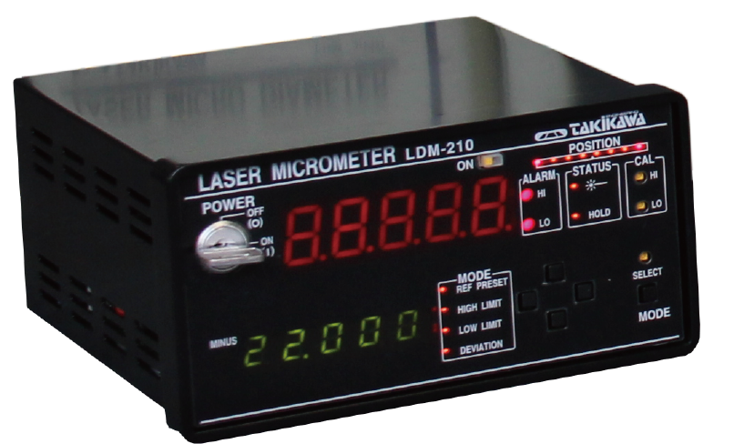
LDM-210 |
LDM-210EX |
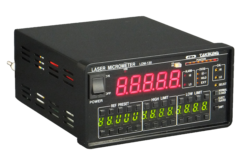
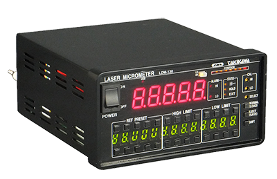
LDM-130 |
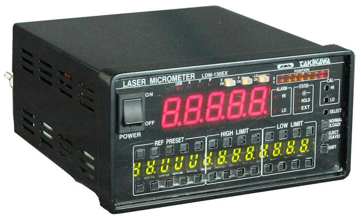
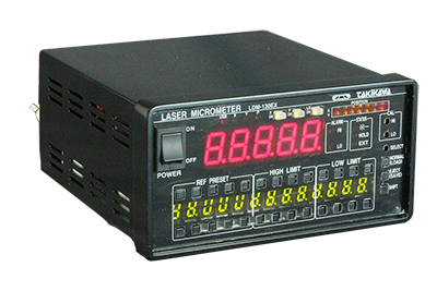
LDM-130EX |
|
CAD file |
|
|
|
|
|
|
|
|
|
|
Number of measurement axes |
1 Axis Only |
2 Axis Maximum |
1 Axis Only |
2 Axis Maximum |
|
Number of samples |
400/2000 scan type |
|
Average times |
1 to 2048 times (12 steps) |
|
Measurement mode |
Arbitrary edge measurement |
|
Wall thickness calculation function |
- |
- |
- |
- |
|
View |
Measured value display Device |
7 segment LED |
|
Number of display digits |
5 digit maximum |
|
Computation contents |
EX mode by using 2 devices |
①Average(X/Y)/2
②Difference
③Ratio X/Y
④Mesurement of large diamiter |
- |
["1", "average: (X + Y) / 2
2 "," Difference: X - Y
3 "," ratio: X / Y
4 "," (XY) / 2
5 "," X + Y
6 "," large caliber measurement "] |
|
Computation content display |
○(EX mode) |
○ |
- |
○ |
|
Work position monitor |
Displayed in 8 LEDs |
|
Analog output |
Number of output channels |
1 channel |
|
Output performance |
Maximum ± 10 V, resolution 12 bits (= about 10 mV resolution), output impedance about 100 Ω, deviation / absolute value switching |
|
Output gain |
1 μm to 1 m / V (10 times step) |
|
Digital outer diameter control connection |
○ |
○ |
○ |
○ |
|
Center value setting |
5 digit |
5 digit segment LED display |
|
Upper / Lower limit tolerance setting |
5 digit |
4 digit segment LED display |
|
Contact output |
- |
- |
Displays the maximum value or the minimum value of averaged value of measured data |
|
USB connector |
- |
- |
Setting Data load/save via USB Memory |
|
Contact output |
Upper and lower limit contact outputs |
1 "a" contact × 2 |
|
Error contact output |
1 "b" contact × 1 (Closed when power is OFF) |
|
Contact rating |
AC 250V 2A (resistance load) |
|
Laser remote terminal |
○ |
○(X/Y common) |
○ |
○(X/Y common) |
|
Hold terminal |
○ |
○(X/Y common) |
○ |
○(X/Y common) |
|
Edge monitoring function |
○ |
○ |
○ |
○ |
|
Self-diagnosis function |
○ |
○ |
○ |
○ |
|
Multi-point calibration function |
○ |
○ |
○ |
○ |
Trigger function
(Max / shake etc.) |
○ |
○ |
× |
× |
|
Offset function |
○ (Since ver 2.15) |
× |
× |
× |
|
Zero set function |
○ |
× |
× |
× |
|
Unit switching function |
× |
× |
× |
× |
|
Program function |
× |
× |
× |
× |
|
Graph display |
× |
× |
× |
× |
|
RS-232C communication |
○(Standerd equipment) |
○ |
|
RS-485 communication |
Optional |
Standerd equipment [Modbus RTU 2 line type] |
|
CC-LINK |
- |
- |
Optional |
|
Ethernet-IP |
- |
- |
Optional |
|
BCD output |
Optional |
6 digit Optional |
|
Pair Detection Code Cord Length |
Standard 5 m, maximum 30 m
(Maximum 120 m if cable extension box is used) |
|
Power supply |
AC 100 to 240 V free power supply 50/60 Hz |
|
Power consumption |
15VA or less |
20VA or less |
|
Operating envirornment |
Temperature: 0 to 45 ° C, humidity: 35 to 85% RH (without condensation) |
Outline dimension
(W × H × D [mm]) |
144 × 72 × 191 [mm] |
|
Weight |
Approx 1.5 kg |
Approx 1.6 kg |
Approx 1.8 kg |
|
Laser Micrometer・Display
|
|
|
|
|
|
|
Outside Dimension : [W * H * D] 144×72×191(mm)
LDM-130 |
|
Outside Dimension : [W * H * D] 144×72×191(mm)
LDM-130EX |
|
Outside Dimension : [W * H * D] 144×72×191(mm)
LDM-110 |
|
|
|
|
|
|
|
|
|
|
|
|
Outside Dimension : [W * H * D] 144×72×191(mm)
LDM-110EX |
|
Outside Dimension : [W * H * D] 216×144×241(mm)
LDM-1000EX |
|
Outside Dimension : [W * H * D] 216×144×241(mm)
LDM-1000 |
|
|
|
|
|
|
|
|
|
Outside Dimension : [W * H * D] 144×72×191(mm)
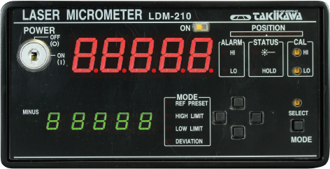
LDM-210 |
|
|
|
|
|
|
|
|
|
|
|
|
|
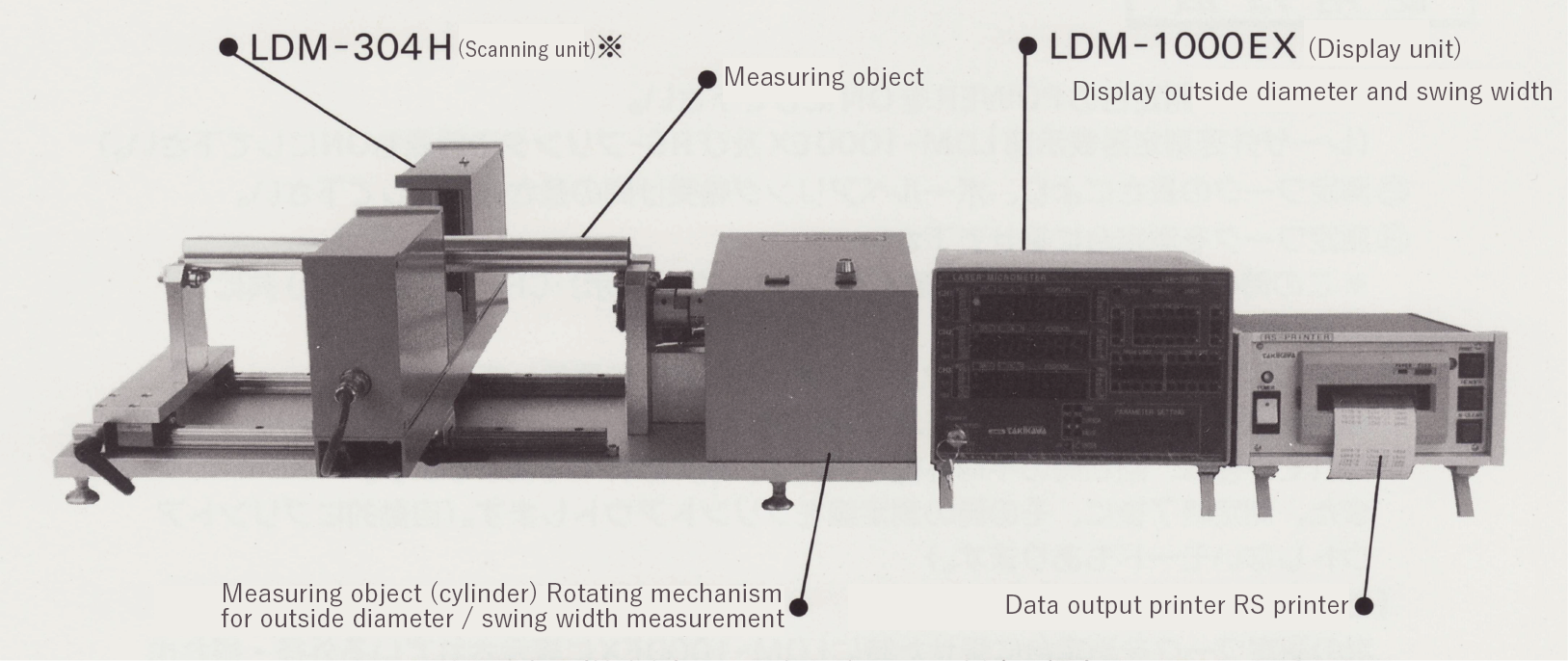
Laser Micrometer / Deflection Micrometer
|
|
|
|
Mearsuring target item |
Cylindrical articles such as rubber rolls, metal rolls, pipes, |
|
CAD file |
304H specification |
|
OD |
Φ 1 to Φ 80 (outer diameter measurement range) |
|
測定分解能 |
1μm |
|
Repeatability |
Outer diameter: ± 2 μm |
|
Runout width: ± 2 μm |
|
Outer diameter accuracy |
± 5 μm (when Φ 40 mm or less) |
|
Runout accuracy |
Within 7 μm |
|
Measurement object length range |
80 mm to 320 mm (Distance between work bearings) |
|
Work receiving |
Bearing receiving |
|
Work rotation speed |
(At the time of Φ 10 mm work) about 3 turns The rotation control method is a speed control motor driving method |
|
Work weight |
5 kg or less |
|
Outer diameter ・ runout width Measuring base weight |
19kg |
|
System weight |
25kg |
|
Power supply |
AC 100 V ± 10% 50/60 Hz 40 VA |
※In case of Φ25mm, LDM-303H-SP is applicable
|
 |
|
* The actual size of the printer paper is about 57 mm wide.
|
|
|
LDM-WTM specification
|
|
|
|
Model No. |
LDM-WTM
(Build-to-order manufacturing) |
|
CAD file |
Rotary unit |
|
LDM-210 |
|
Operating condition |
Used PC |
|
The Windows OS to use should operate comfortably (Operation is not guaranteed for Windows emulator) Be able to use CD-ROM. Screen display size 1024 x 768 or more. PC card Standard TYPE II standard PC card can be installed. Serial port or USB port is installed in the main unit and it is operating. |
|
Used OS |
Micrisoft Windows XP, Vista, 7 (32 bit version: MS company out of license OS or 64 bit version are not guaranteed operation) |
|
Serial communication condition |
19200 bps recommended |
|
communication speed |
Data bit 8 bits, stop bit 1 bit, no parity |
|
Functions |
Measured value display |
Wall thickness measurement value, outside diameter measurement value |
|
Peak value display |
Display maximum value and minimum value during measurement (hold numerical value) |
|
Measurement status display |
Alarm indication, OK indication, Error display and each set value when the upper and lower limit set values ??are exceeded. |
|
Measurement data record |
Measurement place, average value, maximum value, minimum value |
|
Measurement data recording interval |
Minimum 5 degrees (72 circumference divided, measurement time about 5 seconds) |
|
Graph |
Display measurement data in real time, print function |
|
Measurement object shape |
Cylindrical hollow products (transparent objects can also be measured) |
Inside diameter Φ 5.5 mm or more, outer diameter Φ 50 mm or less Length about 30 mm (Inner diameter Φ 5.5 mm or less, outer diameter Φ 50 mm or more is optional) |
|
Measurement accuracy |
± 5 μm |
According to LDM-304H |
|
Configuration system |
LDM-210, LDM-304H, rotary unit, personal computer
|
|
EM series / Eccentricity monitor
|
|
|
Common specification
|
Measurement target |
An electric wire coated with an insulator on a circular conductor |
|
Operating environment |
Temperature 5 to 40 ° C, humidity 35% to 85% RH (without condensation) |
|
Analog output |
Eccentricity (X, Y, R, θ axis), OD deviation (X, Y, average), Outer diameter absolute value (X, Y, average) |
|
Alarm output (relay) |
Outer diameter upper limit, outer diameter lower limit, excess eccentricity amount, error (incorrect position) |
|
File output |
Measurement data can be stored in CF, USB memory, etc. |
|
RS-232C interface |
Data bit 8 bits, Stop bit 1bit, Non-parity, Communication speed 19200 bps recommended. |
|
RS-485 interface |
Optional |
|
Display unit |
EM-PC 2 Panel computer (316 x 256 x 49.2 [mm] 3.5 kg) |
|
Installation resistance value |
Third type installed resistance value (less than 100 Ω) |
|
AC power supply |
AC90 to 240V 50/60Hz less than 50VA |
Individual specification
|
Model No. |
EM-302B
(Build-to-order manufacturing) |
EM-303B
(Build-to-order manufacturing) |
EM-304A
(Build-to-order manufacturing) |
EM-304B
(Build-to-order manufacturing) |
|
Detection unit |
EM-302B |
EM-303B |
EM-304A |
EM-304B |
|
Controller unit |
EM-200B
(Build-to-order manufacturing) |
|
Display unit |
EM-PC2
(Build-to-order manufacturing) |
|
Power Amplifier |
EM-1000
(Build-to-order manufacturing) |
|
Excitation unit |
EM-800
(Build-to-order manufacturing) |
Equipment on the main body |
EM-125
(Build-to-order manufacturing) |
dxf format
CAD file |
Measurement unit |
EM-302B |
EM-303B |
EM-304A |
EM-304B |
|
Control unit |
EM-200 |
|
Excitation unit |
EM-800 |
--- |
EM-125 |
PDF format
CAD file |
Measurement unit |
EM-302B |
EM-303B |
EM-304A |
EM-304B |
|
Control unit |
EM-200 |
|
Excitation unit |
EM-800 |
--- |
EM-125 |
|
Condition of measured electric wire |
Finish OD
(mm) |
0.3 to 5[*1] |
0.3 to 15 |
0.8 to 30 |
0.8 to 45 |
Outer diameter of core wire
(mm) |
0.1 to 3[*2] |
0.1 to 10 |
0.5 to 20 |
0.5 to 35 |
Outer diameter accuracy
[*3] |
±0.002mm |
±0.002mm |
±0.005mm |
±0.005mm |
|
Eccentricity accuracy |
±0.01mm[*4] |
±0.015mm[*4] |
±0.02mm[*5] |
±0.03mm[*5] |
|
General outline Size |
Detection unit |
180 x 175 x 60.4 [mm] |
225 x 260 x 64.4 [mm] |
526 x 530 x 348 [mm] |
606 x 606 x 353 [mm] |
|
Control unit |
202 x 82 x 100 [mm] |
|
Display unit |
316 x 256 x 49.2 [mm] |
|
Power Amplifier |
280 x 137 x 281 [mm] |
|
Excitation unit |
119.3 x 124.6 x 144 [mm] |
--- |
290 x 275 x 203 [mm] |
|
weight |
Detection unit |
2kg |
6kg |
38kg |
57kg |
|
Control unit |
1.9kg |
|
Display unit |
3.6kg |
|
Power Amplifier |
5kg |
|
Excitation unit |
2.2kg |
--- |
15kg |
[*1] Up to 5 mm can be measured depending on usage.
[*2] Up to 3 mm can be measured depending on usage.
[*3] This condition applies to X axis and Y axis respectively.
[*4] Measurement accuracy is guaranteed when the center position of the electric wire satisfies the condition within ± 2 mm of the center position.
[*5] Measurement accuracy is guaranteed when the center position of the electric wire satisfies the condition within ± 5 mm of the center position.
|
Control unit
|
|
|
|
Outside Dimension 121×117×280[mm] EM-200/EM-204 |
|
|
|
|
|
|
|
|
|
|
|
It detects irregularities in the object.
|
|
|
|
|
|
|
|
|
|
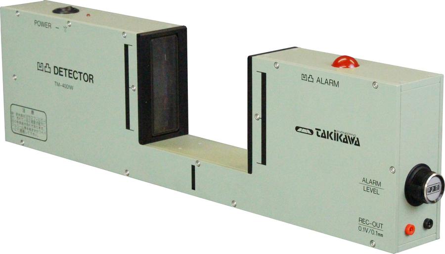
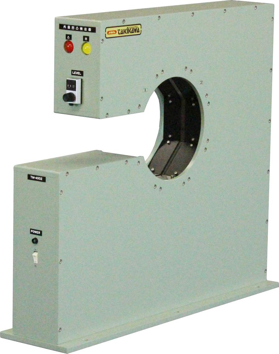
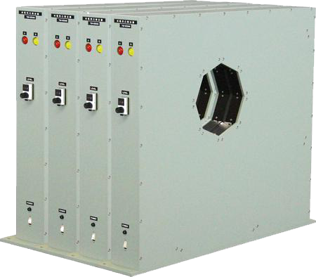
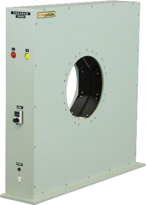
Detector for heavy line TM-4002 |
|
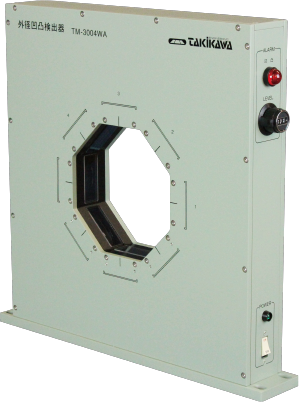
Detector for medium line TM-3004WA |
|
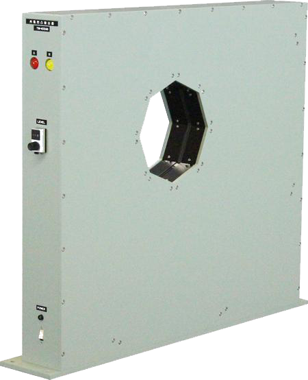
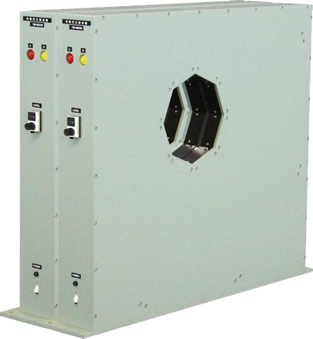
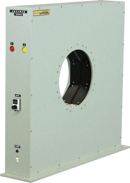
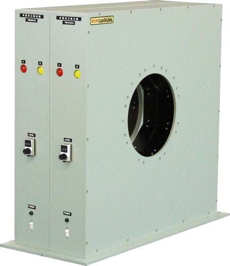
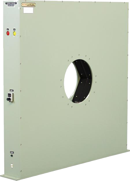
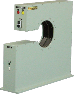
Detector for heavy line TM-6004A |
|
|
|
|
|
|
|
|
|
|
|
|
|
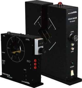
Detector for thin line TM-1003W、Detector for medium line TM-3002W |
|
|
|
|
|
|
|
TM-series Surface Variation Detectors were designed to monitor surface variations in an object by means of emitting light to the object and detecting a difference of interrupted light volume which is affected by the variation.
Those TM-series detectors can be used at production line of all products such as optical fibers, enamel, electric and vinyl wires, communication and power cables, metal and glass rods, plastic tubes, pipes, hose, etc........,
which are required to detect surface variations. |
|
|
-
Features
-
-
It is a device that detects the change in the size of the shadow blocked by the measuring object.
-
Surface Variation can be detected in all production lines such as pipes in general, vinyl cable, communication cable, power cable, plastic, rubber and glass rod etc.
-
It is high speed / continuous detection by non-contact.
-
It is easy to handle.
|
Typical surface variation
|
|
|
|
|
|
|
|
|
|
Blister |
|
Projection |
|
Waviness |
|
|
|
|
|
|
|
|
|
|
|
|
|
Foreign body |
|
Abnormality of transparent pipe |
|
Cover tear |
|
|
|
|
|
|
|
|
|
|
|
|
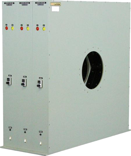
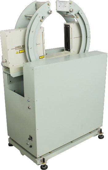
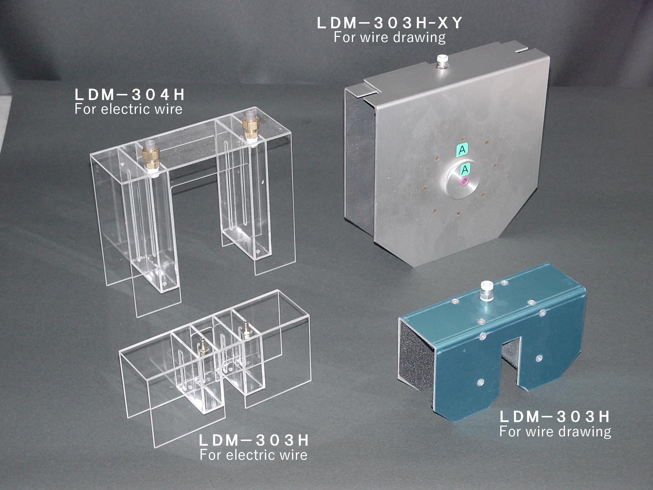
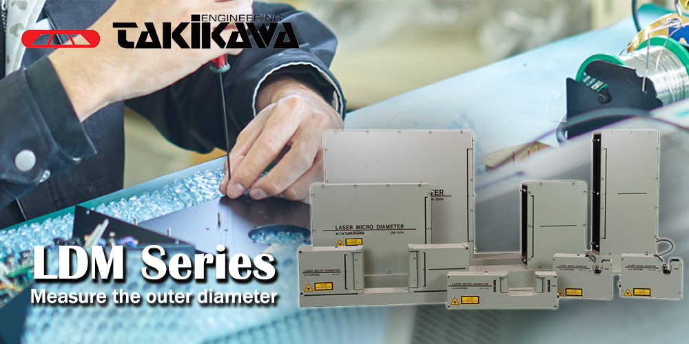
It measures the outer diameter of the object.
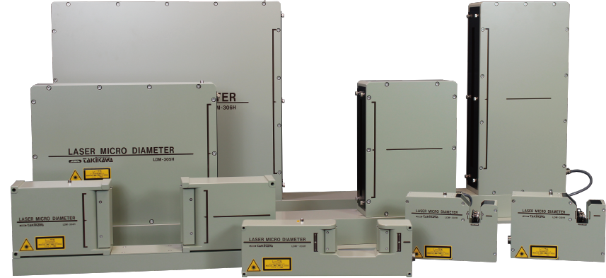
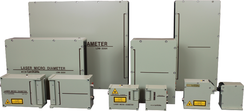
Laser Micrometer LDM series combines the Scanning Unit and the Display Unit according to the various application.
High-performance and low-cost measurement system can be constructed. In response to the voice saying "correspond to every outer diameter", from ultra thin diameter of 0.02 mm to large diameter of several meters, we have a range of models that correspond to every outer diameters.
|
|
|
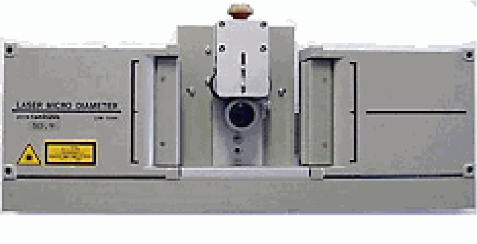
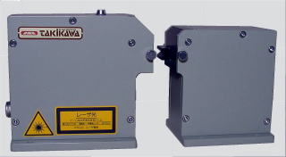
Scanning Unit
|
|
|
|
|
|
|
|
|
|
Single Scanning Unit |
|
Separate type |
|
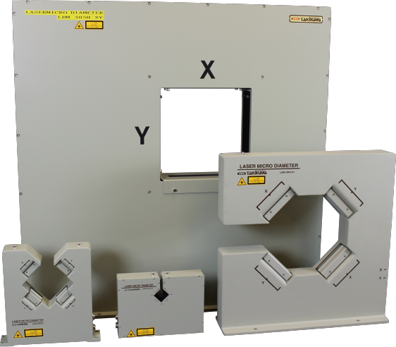
Two-axis Scanning Unit |
|
|
|
|
|
|
|
|
|
|
|
|
|
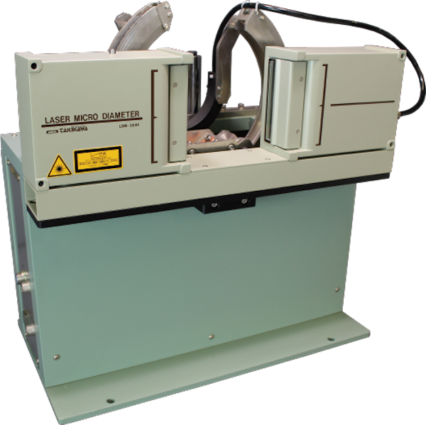
Swing type Scannning Unit |
|
Swing type Scanning Unit
(for Large diameter) |
|
|
|
|
|
-
Features
-
-
A rich lineup will accommodate large diameters ranging from 0.02 mm to several meters.
-
There are also multi-directional coaxial type including orthogonal 2-axis type.
-
There is also a type of a full circumference measurement with swinging.
-
It corresponds to various installation places since there is a separate type.
-
Transparent objects can also be measured since there is no influence of external light such as sunlight.
-
It is possible to measure the object up to 2000 ℃ by option remodeling.
-
An Air purge unit is also available as an option (for some models only)
|
Display
|
|
|
|
|
|
|
|
|
|
For single axis display LDM-130 |
|
For two axis display LDM-130EX |
|
For single axis display LDM-110
(Discontinued product) |
|
|
|
|
|
|
|
|
|
|
|
|
For two-axis display LDM-110EX
(Discontinued product) |
|
For single-axis display LDM-210 |
|
For multi axis display LDM-1000EX |
|
|
|
|
|
|
|
|
|
|
|
|
|
For multi-axis (maximum 5 axes) display LDM-1000 |
|
|
|
|
|
|
|
|
**Various application can be applied by the function of the display unit. |
|
|
-
Features
-
-
Supports CC-LINK(V2) (130/130EX Option)
-
Supports EtherNet / IP (130/130EX Option)
-
MODBUS-RTU(2 Lines)(130/130EX)
-
Able to read and write setting value with USB memory (130/130EX).
-
Supports RS-485 interface (option).
-
Instantaneous value display and calculation of maximum, minimum, average in normal measurement.
-
Calculation of average, difference, sum, ratio, flatness, etc. in multi-axis measurement.
-
Instantaneous value display and calculation of maximum, minimum, and average in full circumference measurement.
-
Large diameter measurement.
-
Sheet thickness measurement.
-
Measurement with multiple lines.
-
Measurement of average wall thickness.
-
Outer diameter control by combination with Dia. control unit.
-
Various control and data collection by combination with PC and PLC.
-
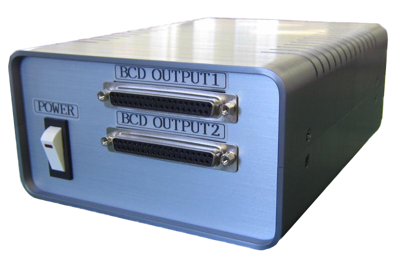
BCD output, RS-232C interface, analog output (BCD output is an option).
-
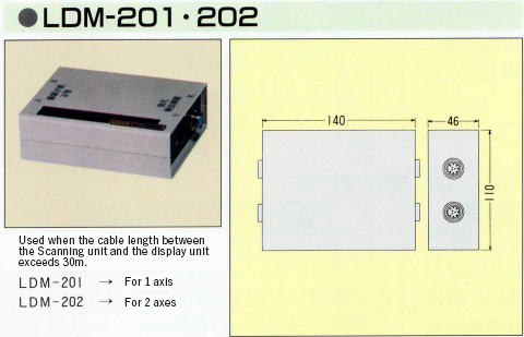
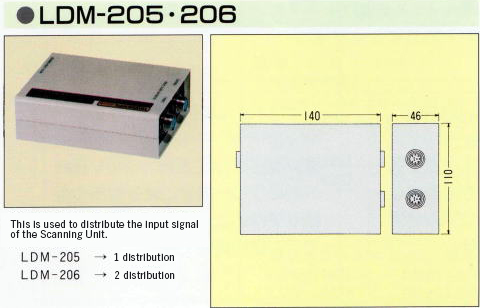
There are Signal Extender (LDM-201, LDM-202) that extend the connection cable to the Scanning Unit, and
Signal Distributer (LDM-205, LDM-206).
|
Products applying Laser Micrometer
|
|
|
Outer diameter / deflection width measuring device (system)
|
|
|
|
**It is a system that puts a rubber covered roll, a metallic roll, the pipe, and the cylinder measurement thing such as Nodou goods on the measurement stand, rotates the measurement thing, and measures the outside diameter and the width of swinging, and outputs the result to the printer. |
|
|
LDM-WTM / Pipe ・ tube outer diameter thickness measurement system (desk type)
(Build-to-order manufacturing)
|
|
|
|
**A surrounding all thickness of meat is measured and the outside diameter in all surroundings of a cylindrical midair products such as the pipe, tubes, and the hoses is graphed on PC in real time and by automatically rotating the measurement thing by 360 degrees. |
|
|
|
|
|
Product & Technology News
LDM Series
Download Catalogue
|